4. Using a 1-3/8 in. hex wrench,
remove the low pressure relief
valve cartridge.
Note: The low pressure relief
valve doesn’t have back-up
rings. There is only one O-ring
in the lower groove.
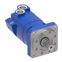
5. Using a 1-3/8 in. hex wrench,
remove the two high pressure
relief valves from valve block.
Note: The high pressure
relief valves have two white
back-up rings and one O-ring in
the lower groove.
High and low pressure relief
settings are preset at the
factory. Stamping on cartridge
identifies setting.
See examples.
Disassembly
Valve Block/
Integral Shuttle End
Cover
1. There are two types of Series
1 hydrostatic motors. If your
motor has an integral shuttle
and low pressure relief valve,
go to step 14 on page 16. If
you have a motor with a valve
block, continue with step 2.
Motors with Valve Block
Disassembly
Seal all open ports. Thoroughly clean exterior of motor before disassembly.
Cleanliness is extremely important when repairing a hydrostatic pump or motor. Work in a clean area, as the level of cleanliness maintained when
repairing the unit may affect performance. After washing the parts with clean solvent, blow dry the parts with filtered, moisture free air. Inspect all mating
surfaces. Replace all damaged parts. Do not use grit paper, files or grinders on finished parts.
Whenever a unit is disassembled, it is a good service policy to replace all seals. Lubricate the seals with petroleum jelly. Use only clean, recommended oil
when assembling the unit. See Hydrostatic Fluid Recommendations on page 28-29 or
publication No. 03-401 & 03-405 for recommended fluids.
CAUTION: Disconnect or disable all
electrical or mechanical power to the pump before
beginning work.
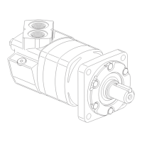
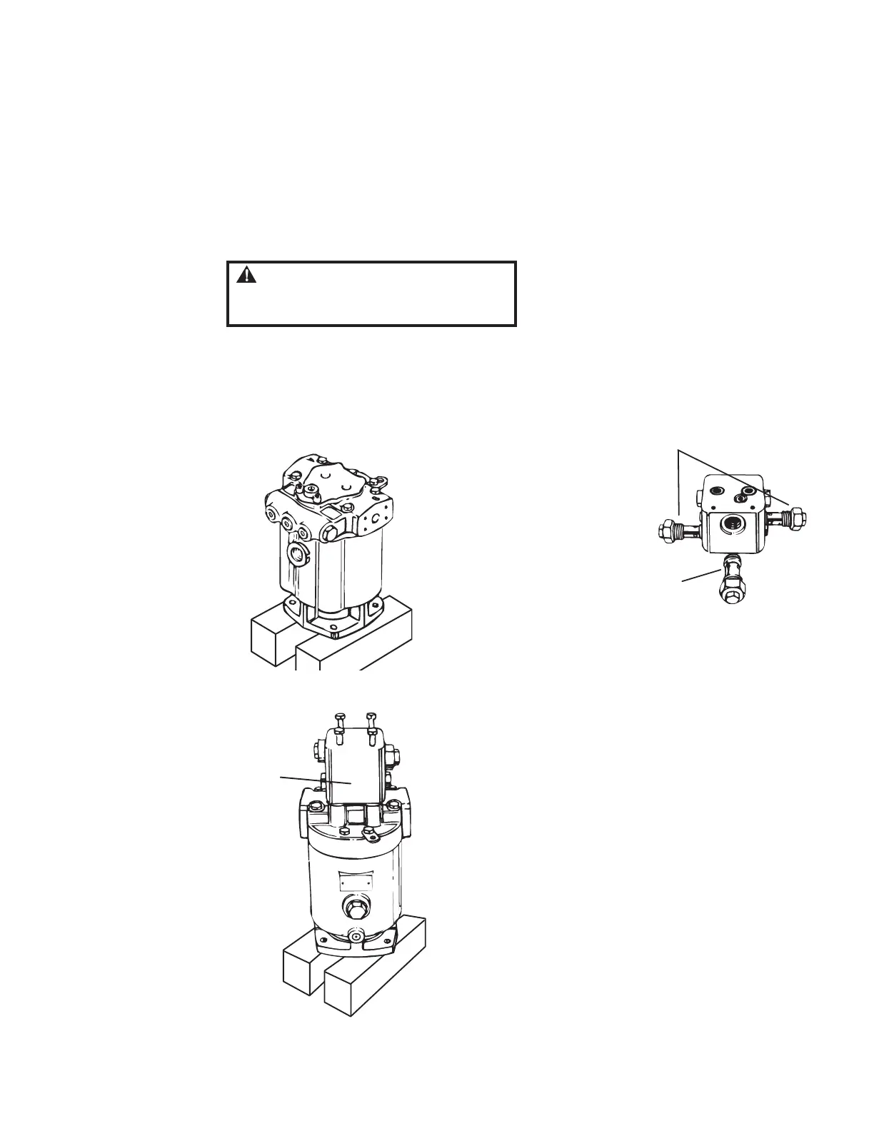
2. Position the motor on its
mounting flange as shown.
Loosen all the relief valves
and plugs in the valve block.
Remove the four bolts that
hold the valve block to the
motor. Then remove the
valve block.
3. Remove O-rings and
back-up rings from
mounting face of
valve block.
 Loading...