Storage
Transformers that will not be placed in service immediately
should be stored with terminal compartment doors closed
and sealed to prevent damage to bushings or other
attachments.
Quality standards
ISO 9001 certified quality management system
Installation
Installation location
The transformer must be located to meet applicable fire
codes. For indoor installations, the installation location must
meet the requirements of the National Electrical Code
(NEC
®
) with sufficient space requirements and proper over-
current protection as specified by the listing body that has
jurisdiction over the installation.
These pad-mounted transformers are built to operate
at altitudes up to 3300 feet at 30 °C average and 40 °C
maximum ambient, unless otherwise specified. Before
operating a standard transformer at higher altitudes, contact
your Eaton representative.
Mounting the transformer
The transformer should be mounted on a level concrete
pad. The pad should be strong enough to support the
weight of the transformer. The site must be adequately
prepared to prevent the transformer from tilting beyond two
degrees from horizontal.
Tilting beyond two degrees may cause internal components
to come out of the oil and/or cables to mechanically stress
the bushings and bushing gaskets. Excessive tilt (beyond
two degrees) can result in a lower dielectric strength for the
transformer than the basic insulation level (BIL) listed on the
nameplate. Reduced BIL can result in an internal dielectric
breakdown with a risk of explosion, tank rupture, or fire.
To maintain full cabinet security, the transformer tank and
cabinet base have provisions for installing cleats to secure
transformer to pad. If gaps still exist between the cabinet
and pad after cleating the cabinet, the installation will not
provide the security needed to prevent tampering by the
public. Add a permanent mortar seal to fill the gaps.
Pre-service inspection (exterior)
New transformers, or transformers which are being
activated after a period of storage, should be thoroughly
inspected before being connected to the power distribution
system to identify damage which may have occurred during
storage.
1. The transformer exterior should be inspected for nicks,
dents, and scratches. Repair damage to weather-
resistant finishes promptly.
2. The tank cover and manhole/handhole cover seals
and all gaskets or seals at bushings, gauges, fuses,
operating devices, etc., should be inspected for
evidence of insulating liquid seepage. Repair leaking
or improperly tightened gaskets and seals before the
transformer is placed in service.
3. Under normal conditions, the transformer leaves the
factory with a slight positive pressure in the tank
over the oil. However, due to changes in atmospheric
conditions, the unit may arrive under vacuum (negative
pressure). This is itself is not cause for concern, however
continued absence of either negative or positive
pressure may indicate a leak at a gasket seal or tank
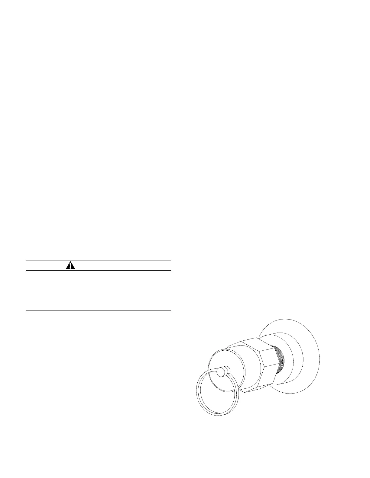
seam, and require further investigation. To leak test
transformer, remove the pressure relief valve (see Figure
1) and pressurize the headspace to ensure that there are
no leaks. The test pressure should not exceed 7 psig.
The established pressure should be maintained for at
least four hours to ensure that all the seals are proper.
Figure 1. Pressure relief valve.
WARNING
Fire Hazard. Non-level installation of transformer
can result in fire and cause severe personal injury or
death. Prepare transformer installation site such that
transformer does not tilt more than two (2.0) degrees
from horizontal while the transformer is in service at
the site.
2 Three-phase pad-mounted compartmental type installation and maintenance instructions MN202001EN August 2015
 Loading...


