Isolating and grounding a cable requiring repair
Step 1.
De-energize cables
•
Open switches at both ends of the cable to be isolated.
Refer to Figure 4.
•
Determine that there is adequate working room around
the connectors for parking the insulated standoff bush-
ings and training the cables.
•
Determine that there is adequate working room for
handling hotstick around apparatus cabinet.
•
Place insulating rubber blanket on the ground directly in
front of connectors.
•
Inspect and test all operating equipment for serviceability.
•
Connect grounding elbow to system ground.
•
Connect ground leads of protective caps to system
ground.
Step 2.
Determine that cables are de-energized
•
Remove 200 A protective cap or arrester from PUSH-OP
connectors using hotstick and set aside in a clean,
protected area.
•
Insert test probe into 200 A interface using hotstick.
Refer to Figure 5.
•
Test for voltage by fuzzing or by using voltage detector
designed for connectors. Remove probe after testing.
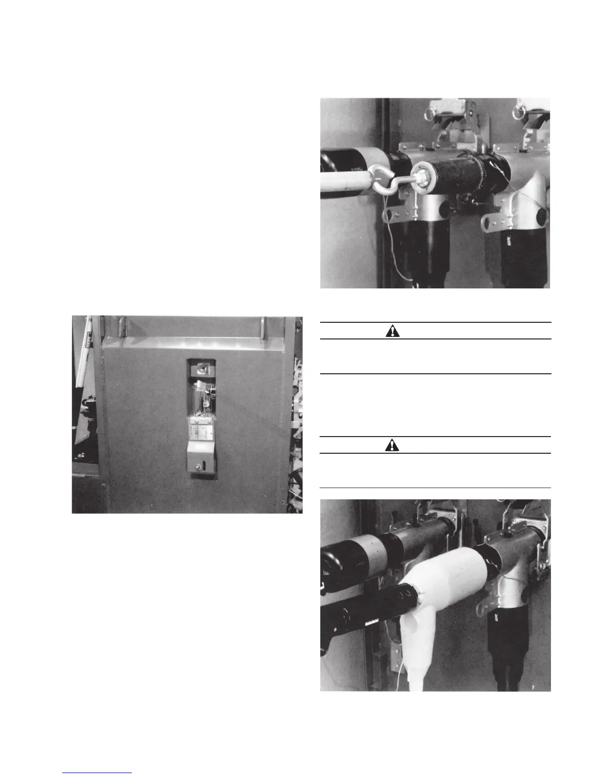
Step 3.
Provide a visible ground
•
Close grounding elbow into PUSH-OP 200 A interface
using a hotstick. Refer to Figure 6.
Figure 4. De-energized cables.
Figure 5. Test for voltage with test probe.
Figure 6. Provide a visible ground with a grounding
elbow.
WARNING
Hazardous Voltage. Do not proceed until cable is de-
energized. Failure to comply may result in death, severe
personal injury or equipment damage.
WARNING
Hazardous Voltage. Ground all three phases (Steps 2
and 3) before proceeding. Failure to comply may result
in death, severe personal injury or equipment damage.
3600 A PUSH-oP DeADbreAk connector oPerAtion inStrUctionS MN650011EN May 2017
 Loading...


