Analog remote/latching mode
This feature is set at FC 70. Up to three independent values
of voltage reduction are possible. Levels 1, 2, and 3 are
programmed at FC 73, FC 74, and FC 75, respectively.
Voltage Reduction input 1 activates the voltage reduction
programmed at FC 73; Voltage Reduction input 2 activates
the voltage reduction programmed at FC 74; and latching
both contacts activates the voltage reduction programmed
at FC 75. Each of these function codes may be set from 0.1
to 10.0%. Read the section on Discrete voltage reduction
above for information on the voltage reduction contact
points.
Analog remote/pulse mode
This feature is set at FC 70. Voltage Reduction Point 1 is
described in the Discrete voltage reduction section. The
contact is pulsed (momentarily closed) rather than latched
closed to activate this feature. Each closure and waiting
period between closures is expected to be at least 0.25
seconds in duration.
The number of steps of pulsed reduction, up to 10, is
programmed at FC 76. The percent reduction per step is
programmed at FC 77. The present voltage reduction step
is display at FC 78. Starting at zero percent reduction,
every time Voltage Reduction Point 1 is pulsed, one step of
reduction is added to the accumulated total. Pulsing to one
step higher than the programmed number of steps returns
the voltage reduction to zero. If Voltage Reduction Point 2
is assigned to one of the other GPI points or and auxiliary
contact point, a pulse to that point returns voltage reduction
immediately to zero.
EXAMPLE: If the number of steps is 3 and the percent per
step is 1.5%, four successive pulses of voltage reduction
will cause the following percentages of reduction: 1.5, 3.0,
4.5, and 0.
5 J
V
9
B
R
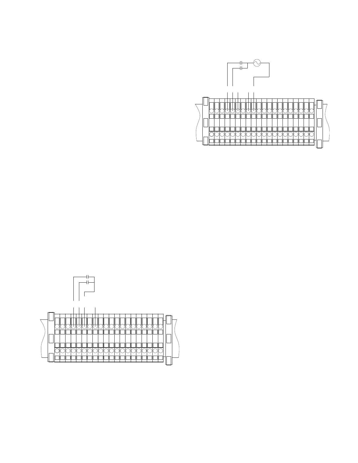
Figure45. Dry contact connections for remote latching
and pulse mode with Voltage Reduction Point 2 reas-
signed to GPI 2
5 J
V
9
B
R
G
Figure46. Whet contact connections for remote latch-
ing and pulse modes with Voltage Reduction Point 2
reassigned to GPI 2
Tap-to-Neutral
The Tap To Neutral Feature enables a user to tap a voltage
regulator to neutral and then maintain that position for as
long as desired. During this time, auto operation will be
blocked. To utilize the Tap To Neutral feature, two elements
are required.
The first required element is to enable Tap To Neutral.
Enabling can be done by setting FC 170 on the control to
On or by checking a Tap To Neutral box in ProView NXG. The
second element required for Tap To Neutral is activation. Tap
To Neutral is activated using either an analog input or digital
SCADA data point.
As a default, GPI 2 (the J terminal on the control back panel)
is used as the analog input to active the feature. Using
a relay to close in 120 Vac or ground to the terminal will
activate Tap To Neutral.
The digital SCADA point Configurable Logic Output
From SCADA Tap to Neutral Activate can also be used
to activate Tap To Neutral. This digital SCADA point can be
found in the default CL-7 DNP map as binary output point 38
(BO-38). In the CL-7 MODBUS default map, the point can be
found in Binary Input Registers point 21 (BI-21).
141
INSTALLATION, OPERATION, AND MAINTENANCE INSTRUCTIONS MN225003EN April 2018
CL-7 Voltage Regulator Control
 Loading...


