Fault detection
The fault detection feature will compare system load current
measured by the voltage regulator with a reference value,
and determine if the load current rises above a defined fault
current threshold level for a defined period of time.
The Fault Detection feature can be enabled using FC 640 on
the control HMI or by checking a box in the Fault Detection
dialog box in ProView NXG.
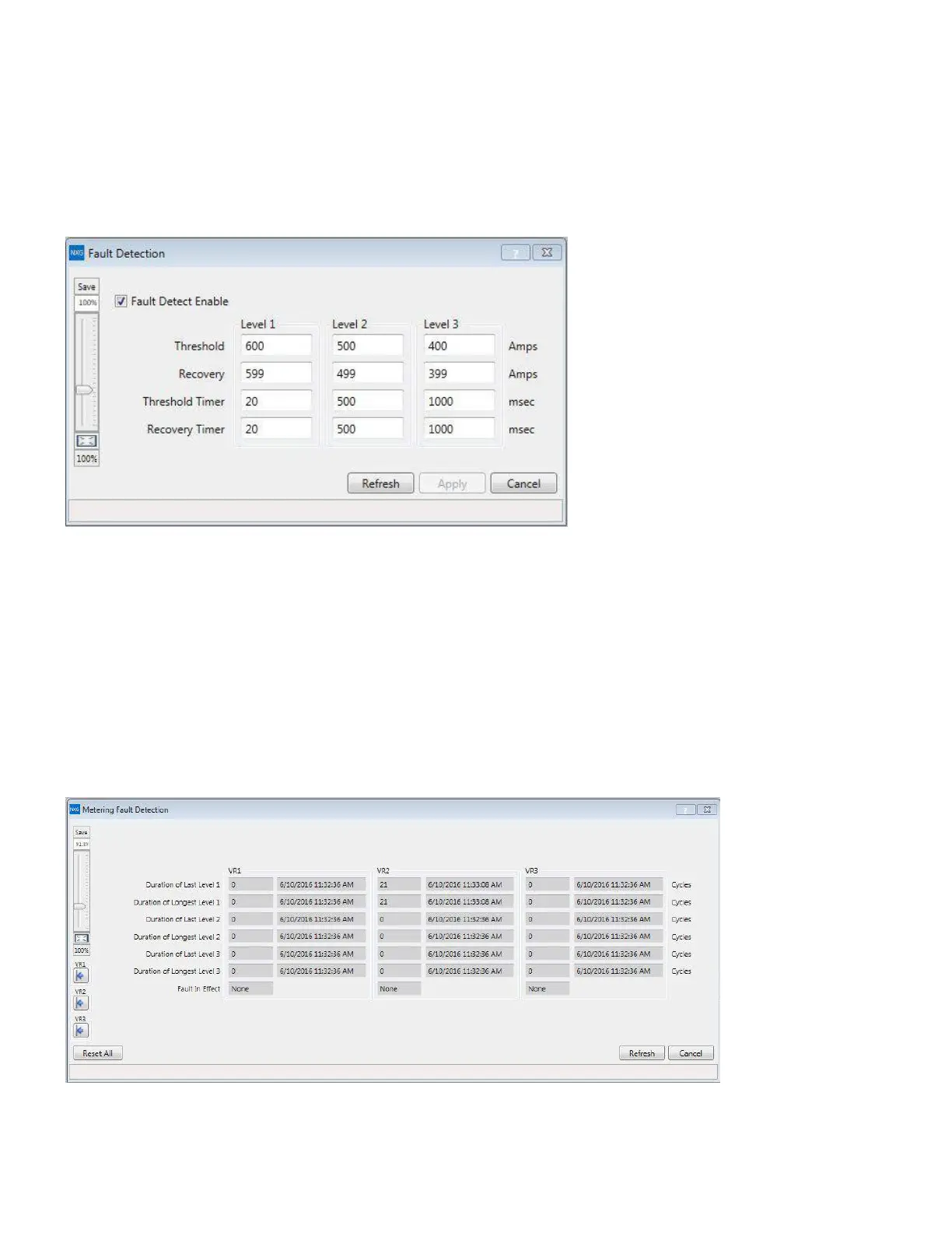
Figure 56. Fault Detection settings dialog box
The Fault Detection feature will enable the control to
compare system currents against three unique fault current
levels. Each fault current level contain both a current
threshold in amps and threshold timer in milliseconds.
When the control detects that the system current level has
exceeded a defined fault current level and remains above
that level for the time period defined by the Threshold
Timer, the control will record the fault current as an event
in the control's Sequence of Events recorder. When the
fault current falls below the defined Recovery current level
for the time period defined by the Recovery Timer, the
control will reset Fault Detection and record another event
indicating that the fault has ended. Fault Detection settings
can be made using the dialog box shown above (Figure 56)
in ProView NXG or through the control HMI using function
codes found in the control nested menu Features > Fault
Detection. There is one set of Fault Detection settings
which applies to all three voltage regulators when using a
multi-phase control.
It is also possible to record the total time duration of the
fault events. The last fault event and longest fault event are
recorded with a date and time stamp which can be viewed
using the control HMI or in the Metering Fault Detection
dialog box (Figure 54) in ProView NXG. Fault Detection
event recording is available for up to three connected
voltage regulators when using a multi-phase control.
Figure 57. Metering Fault Detection dialog box
156
INSTALLATION, OPERATION, AND MAINTENANCE INSTRUCTIONS MN225003EN April 2018
CL-7 Voltage Regulator Control
 Loading...


