2. If the regulator nameplate identifies the load control
signal as a value other than 120 volts for the system
voltage used, set the ratio correction using RCT1 as
show in the following examples:
Example 1: If the control voltage is listed as 115 V:
•
Calculate 115 - 120 = -5 volts.
•
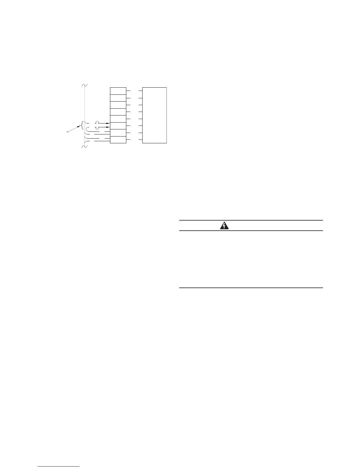
Obtain a -5 difference by placing lead # 17 on
RCT1 - 20 and placing lead # 25 (the end not connected
to the 120 terminal on the RCT terminal block) on
RCT1 – 25 (20 - 25 = -5 volts). See Figure 15.
•
The Overall PT ratio entered at FC 44 would be
determined by dividing the system voltage by the
"ratio corrected" control voltage. For example: If
the system voltage is 7620 and the control voltage
was corrected to 120 V, the Overall PT Ratio will be
7620/120 = 63.5.
Example 2: If the control voltage is listed as 125 V:
•
Calculate 125 - 120 = +5 volts.
•
Obtain a +5 difference by placing lead # 17 on
RCT1 - 25 and place lead # 25 (the end not connected
to the 120 terminal on the RCT terminal block) on
RCT1 – 20 (25 - 20 = +5 volts). See Figure 15.
•
The Overall PT ratio entered at FC 44 would be
determined by dividing the system voltage by the
"ratio corrected" control voltage. For example: If
the system voltage is 7620 and the control voltage
was corrected to 120 V, the Overall PT Ratio will be
7620/120 = 63.5.
3. If the regulator nameplate identifies the control signal
as other than 120 volts, but it is not able to exactly be
corrected to 120 volts, select the RCT compensation
that will correct it as close as possible to 120 V. The
Overall PT Ratio would be calculated by dividing the
system voltage by the ratio corrected control voltage.
Example: If the control voltage is listed as 123.5:
•
Calculate 123.5 – 120 = +3.5 volts
•
Obtain a +3 difference by placing lead #17 on
RCT1 – 23 and placing lead #25 (the end not connected
to the 120 terminal on the RCT terminal block) on
RCT1 – 20 (23 - 20 = +3 volts). See Figure 15.
•
The Overall PT ratio entered at FC 44 would be
determined by dividing the system voltage by the
"ratio corrected" control voltage. In this example, the
control voltage was corrected by 3 volts and will be
123.5 – 3.0 = 120.5. If the system voltage is 7620,
the Overall PT Ratio will be 7620/120.5 = 63.2.
Control programming
Once the control is installed, power the control for
programming.
Powering the control using line power
The control can be powered for programming by connecting
the regulator to the power distribution lines. It is important
to perform the following steps before beginning this
process so that the regulator does not begin to operate
before it is programmed:
1. Open the V1 (and V6 if present) switches on the back
panel
2. POWER switch set to OFF
3. CONTROL FUNCTION switch set to OFF
4. Remove the 6-amp motor fuse
There are two scenarios for powering using line power:
1. Bypass switching is performed using 3 separate
switches: If the bypass switches being used are not
single-pull type, the control can be powered by closing
the source switch only.
2. Bypass switching with a single-pull switch or 3 separate
switches: The control can be powered by closing the
disconnect switches, opening the bypass switch and
putting the regulator fully into service. Use locally
approved processes for regulator installations. Make
sure that the regulator is in the neutral position before
starting the process.
To power the control, while the CONTROL FUNCTION
switch remains in the OFF position, close the V1 switch
on the back panel and move the POWER switch to the
INTERNAL position.
DANGER
Explosion Hazard. Voltage regulators are subject to high
circulating current during bypass switching. Refer to
Service Information MN225003EN Voltage Regulator
CL-7 Series Control Installation, Operation, and
Maintenance Instructions for information on the CRA
Control, and refer to the instruction manual supplied by
the voltage regulator manufacturer for specific safety
procedures for bypass switching. Failure to comply will
result in severe personal injury or death. VR-T214.0
36
30
31
32
33
34
35
37
RCT1
30
27
25
23
21
20
120
COM
12
25
25
17
WIRE COLOR CODE
10 - Black
12 - White
17 - Black
18 - White
25 - Black
10
18
Move these leads
Figure 15. Ratio Correction Transformer connections.
20 CL-7 control replacement assembly installation instructions and service information MN225017EN October 2016

 Loading...


