2OPERATING INSTRUCTIONS MN280067EN July 2017
Type MET electronic recloser control tester operating instructions
Description and use of operating controls
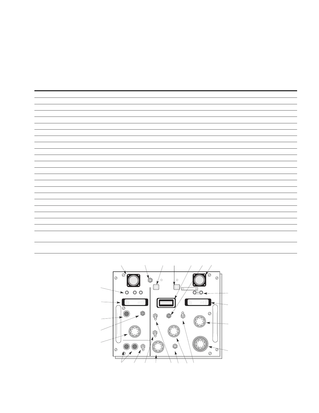
Table 1 lists and describes the operating controls and
instrumentation of the tester. All the devices are mounted
on the front panel and are keyed to Figure 2, a close-up
view of the front panel. Reference designations are labeled
on the front panel of the tester.
Table 1. Description and use of operating controls, and identification
Index no (fig 2) Reference designation Description Purpose and use
1 S-1 Power switch Energizes AC input to tester.
2 Power fuse (2A-250 V type AGC) Protects power input circuits.
3 S-6 Test selector switch Selects the DC meter scale.
4 S-7 Battery load test switch Checks battery voltage under load.
5 Meter fuse (2A-250 V type AGC) Protects DC meter.
6 DC meter Measures DC voltage or current.
7 Battery test terminals Interface for battery test cable.
8 Recloser cable receptacle Interface for recloser test cable.
9 S-8 Recloser test switch Operates recloser electrically.
10 Recloser simulator—open light Indicates an open recloser during control testing.
11 Recloser simulator—closed light Indicates a closed recloser during control testing.
12 Timer Measures time of test.
13 S-10 Timer reset button Resets timer back to zero after timing operation.
14 Control cable receptacle Interface for control test cable.
15 External ammeter jacks Connects external ammeter to tester.
16 MA-1 Ac ammeter Measures AC test current.
17 S-4 Ammeter range switch Selects AC Ammeter scale.
18 TR-1 Fault-current adjust Determines test-current level.
19 S-2 Fault-current switch Allows presetting fault currents and applies test current to control.
20 S-3 Time selector switch Selects control function to be checked.
21 S-5 Phase selector switch Selects the phase to be tested.
22 S-9 Low-ground trip—normal switch Tests ground minimum-trip levels down to 5.8 amps.
23 S-11 Display mode switch
Continuous: Display shows time as it is accumulated.
Update: Display shows time at end of each interval.
24 S-12 Auto reset switch
Off: Display will continually accumulate time until manually reset.
On: Display will automatically reset at beginning of each interval.
12.5
12
3
4
5
6
7
8 9 10 11 12 13 14
15
16
17
18
19 202122 2324
Figure 1. Tester controls and instrumentation (See Table 1 for parts identification)

 Loading...


