8 KA369R, KA542R, AND KA57WE AUXILIARY SWITCH KIT INSTALLATION AND ADJUSTMENT INSTRUCTIONS MN280031EN
Adjustment
This switch is composed of one, two, or three sections,
each of which has two sets of contacts designated “a” and/
or “b”.
All “a” contacts are open and “b” contacts are closed when
the recloser is tripped.
Contacts can be adjusted in the field for either “a” or “b”
operation by repositioning the cams inside each switch
section.
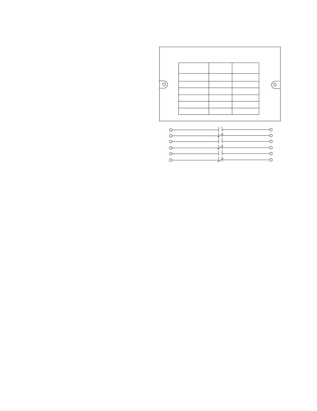
The nameplate attached to the switch cover shows
the original factory setting (Figure 14). If the switch is
re-adjusted the nameplate should be revised accordingly.
To change any cam position:
1. Remove the auxiliary switch housing cover.
2. Remove the four screws and lockwashers securing the
housing base plate to the recloser head.
3. Lift off the entire switch assembly.
4. Remove the cotter pin and collar from the square shaft.
5. Remove the hex nuts and lockwashers from the two
long machine screws holding the switch sections to the
base plate.
6. Starting with the bottom section, lift the cams off the
square shaft.
(continued on next page)
Two Position Auxiliary Switch
115/230 Volts 30/15 Amps.
1
3
5
7
9
11
2
4
6
8
10
12
Switch
Circuit
"a"
Contact
"b"
Contact
1-2
3-4
5-6
7-8
9-10
11-12
X
X
X
X
X
X
Schematic Representation of Contact
Positions Shown on Nameplate
Figure 14. Nameplate and schematic diagram for typical
three-stage switch.

 Loading...


