Home
Eaton
Cables and connectors
GridAdvisor Series II
Eaton GridAdvisor Series II User Manual
4
of 1
of 1 rating
188 pages
Give review
Manual
Specs
To Next Page
To Next Page
To Previous Page
To Previous Page
Loading...
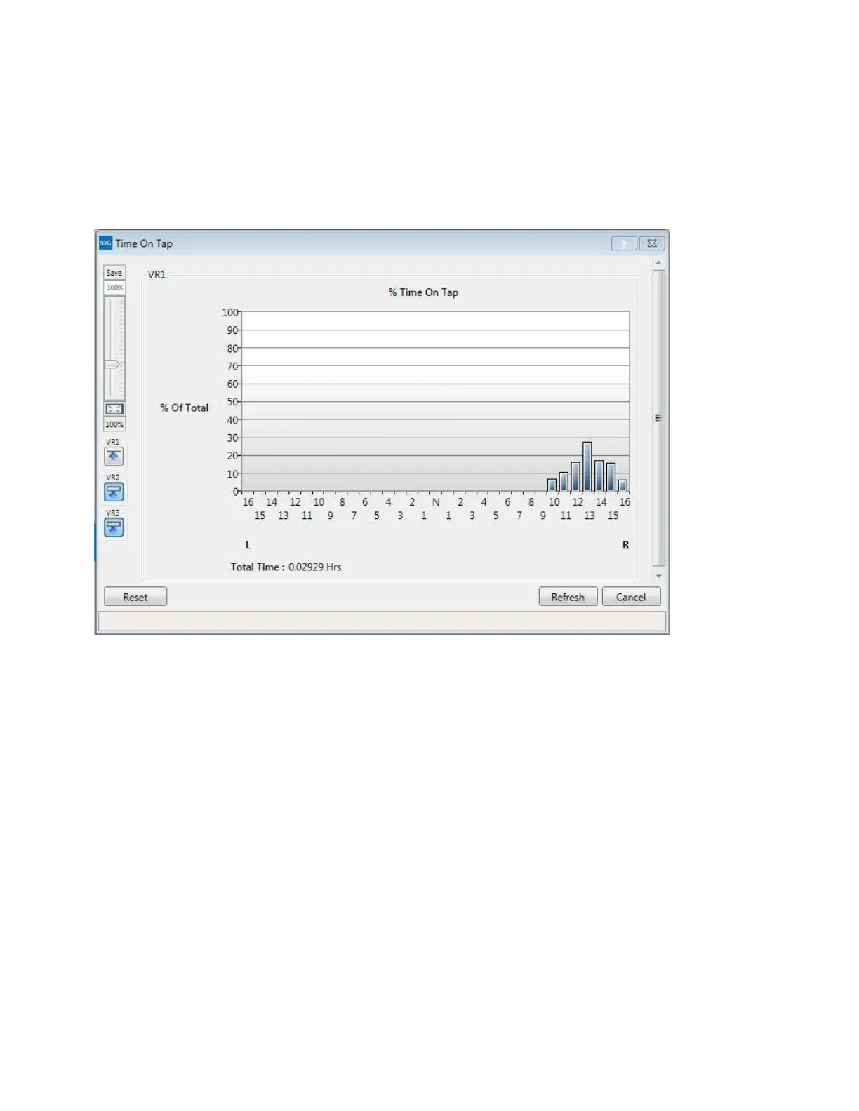
TIME-ON-T
AP™ feature
The
TIME-ON-T
AP™ feat
ure logs the percent
age of time
spent on eac
h t
ap-c
hanger position.
The
TIME-ON-T
AP
data is only viewable using P
roView NXG sof
tware and is
presented in bar graph format; see
Figur
e 54
.
Figur
e 54.
TIME-ON-T
AP sample graph
153
INST
ALLA
TION, OPERA
TION,
AND MAINTENANCE INSTRUCTIONS
MN
225003EN April 2018
CL
-
7 V
o
ltage Regu
lato
r C
ontro
l
160
162
Table of Contents
Disclaimer of Warranties and Limitation of Liability
2
Table of Contents
3
Safety for Life
6
Safety Information
6
Safety Instructions
6
Product Information
7
Introduction
7
Description
7
Read this Manual First
7
Additional Information
7
Acceptance and Initial Inspection
7
Handling and Storage
7
Quality Standards
7
Control Panel Layout
8
Lower Panel (Grey)
9
Power Switch
9
Control Function Switch
9
Section 1: Control Front Panel
9
Connecting Power to External Source Terminals
10
120 Vac Application with Eaton's Cooper Power Series 120 V Control
11
CL-7 Control Panel
11
240 Vac Application with Eaton's Cooper Power Series 120 V Control
13
Display
16
LCD Display Contrast
16
Upper Panel (Black)
16
Alphanumeric and Symbol Keys
17
Keypad
17
Parameter Access and Editing
17
Scroll Arrow Keys
18
Short-Cut Hot-Keys
18
Standard Keypad Hot-Key Assignments
18
Data Ports
19
Indicator Leds
19
Multi-Phase Indicators
19
Status Indicators
19
Control Specifications
20
Mounting the Control
20
Setting the Control for Service
20
Section 2: Control Installation
20
Operational Check
21
Pre-Installation Check
21
Setting the Control for Multi-Phase Service
21
In-Service Check
21
Control Bench Testing
22
Field Calibration Check
22
Removal from Service
23
Determining Neutral Position
23
Return the Regulator to Neutral
23
Removal of Control
24
Replacement of Control
24
Basic Programming
25
Programming for Basic Operations
25
Section 3: Initial Control Programming
25
Multi-Phase Leds and Forward Arrow
26
Multi-Phase Programming
26
Programming for Reverse Power and Additional Features
26
Power the Control for Programming
27
Programming and Reconfiguring for Different Voltage Systems
27
Steps for Changing System Voltage
27
Allowable System Voltages and Calculation of Overall PT Ratio
28
RCT Ratios
28
Nameplates, 60 Hz Regulator and 50 Hz Regulator Shown
29
Determination of Leading or Lagging in Delta-Connected Regulators
30
Automatic Operation
31
Control Operation
31
Manual Operation
31
Self-Test
31
Section 4: Control Operation
31
Security System
32
Remote Security Override
32
Security Codes
32
Basic Control Operations
33
Set Voltage
33
Bandwidth
33
Regulator Configuration
33
Voltage-Averaging Mode
34
Internal PT Ratio
34
Current Transformer Primary Rating
34
System Line Voltage
34
Quik-Start Setup
35
Section 5: Control Programming
35
Quik-Start Set-Up for Basic Regulation
36
Function Menu
37
Forward Set Voltage Volts
53
Function Codes
53
Total Operations
53
Fwd Line Drop
54
Load Voltage
54
Source Voltage Secondary
54
Kva Load
56
Kw Load
56
Power Factor
56
Current THD
57
Kvar Load
57
Line Frequency
57
Voltage THD
57
Special Functions
66
Last Self-Test Results
76
Security Override
76
Password Admin
77
Password Modify
77
Password Operate
77
Self-Test Complete
77
Alarms
84
Motor Power Source Selection
84
Neutral Sync Retry Count
84
Nominal Sec Load Voltage
84
Reset
84
Sequence of Events (SOE)
84
Battery Voltage
85
Tap to Neutral
85
Tap to Target
85
Enter Security Code – FC 99
125
Initial Press Reset Message
125
Self-Test - FC 91
125
Special Functions
125
An Actual Alarm Display Example
126
Instantaneous Metering and Counter Quantities
126
Maintenance Quantities
126
Sequence of Events (SOE)
126
Displayed During Self-Test Message
127
Indication Messages
127
Power-Up/Reset Conditions
127
Calendar/Clock
129
Demand Task Operation
129
Metering
129
Section 6: Control Features
129
Tap Position Indication (TPI)
130
Source-Side Voltage
130
Differential Voltage
130
Source Voltage
130
Reverse Power Operation
131
Locked Forward Mode
131
Locked Forward Mode Operation
132
Locked Reverse Mode Operation
132
Locked Reverse Mode
132
Reverse Idle Mode
132
Bi-Directional Mode
133
Reverse Idle Mode* Operation
133
Bi-Directional Mode Operation
134
Neutral Idle Mode Operation
134
Neutral Idle Mode
134
Co-Generation Mode
135
Reactive Bi-Directional Mode
135
Co-Generation Regulation Points
135
Co-Generation Mode Operation
135
Bias Bi-Directional Mode
136
Reactive Bi-Directional Mode Operation
136
Bias Bi-Directional Mode Operation
136
Bias Co-Generation Mode
137
Bias Co-Generation Metering
139
Reverse Co-Generation Mode
140
Reverse Co-Generation Regulation Points
140
Reverse Co-Generation Operation
140
Multi-Phase Voltage Regulation
141
Multi-Phase Parameters
141
Voltage Averaging
141
Max Deviation
141
Multi-Phase Control Display
142
Multi-Phase Regulation Settings
142
Auto Tap Dead Phase
142
Deltacalc Feature
143
Deltacalc Settings
143
Deltacalc Settings for Open Delta
143
Open Delta Voltage Regulation
143
Voltage Limiter
144
Deltacalc Settings for Closed Delta
144
Voltage Reduction
145
Adaptive ADD-AMP
145
Local/Digital Remote Mode
145
Soft ADD-AMP Feature
145
Supervisory Control and Data Acquisition (SCADA)
145
Digital SCADA
146
Local Operator Security
146
Supervisory Switch
146
Control Switch
146
Analog Remote/Latching Mode
147
Analog Remote/Pulse Mode
147
Tap-To-Neutral
147
Control Panel Connection
147
Tap-To-Target
148
Alternate Configuration
148
Remote Motor Control and Auto-Tap Blocking
148
Auto-Restore Local (ARL)
149
Configurable Logic
149
Fooler Voltage Scheme
149
Transducer Connections
149
Section 7: Advanced Control Features
151
Metering-PLUS Feature
151
Compensated Voltage
151
Operation Analysis Using Metering-PLUS Feature
151
Load Current
152
Blocking Condition Priorities
153
Tap Position
153
Saving Configuration Settings, FC 950
155
USB Memory Device
155
USB Memory Drive Functions
155
A USB Memory Device in the Data Port
155
Loading Configuration Data, FC 951
156
Communication Ports
156
Remove Device, FC 953
156
.CSV Files, FC 954
156
Protocols
156
Auxiliary Input and Output
157
Optional I/O Contact Module Connector
157
Configurable Logic
157
Contact I/O Option Module Input Ratings
159
Output Ratings
159
Maximum Switching Power
159
Maximum Output Switching Graph
159
Alarms
160
Data Profiler
160
Sequence of Events (SOE)
160
TIME-ON-TAP Feature
161
Preventive Maintenance Tapping
162
Leader/Follower Scheme
162
Duty Cycle Monitor
162
PMT Mode B
162
Voltage Sag Monitoring
163
Fault Detection
164
Fault Detection Settings Dialog Box
164
Metering Fault Detection Dialog Box
164
Heater
165
Customer Supplied Battery Power
165
Battery Options
165
DC Power Supply (13.5 VDC)
165
No Control Power
166
External Check
166
Diagnostic Error Messages
166
Section 8: Troubleshooting
166
Defining the Problem
166
Control Panel Troubleshooting
166
Control Not Installed on Regulator
167
No Input Voltage
167
Control on Regulator
167
Tap-Changer Operation Troubleshooting
168
Indication Messages When Using Edit Key
168
Motor Capacitor Problem
169
Tap Position Out-Of-Sync
169
Regulator will Not Tap Beyond a Certain Tap Position
169
Operation Counter Does Not Indicate Tap Change
169
Check FC 56, Reverse Sensing Mode
170
Check FC 69, Auto Operation Blocking Status
170
Check FC 170, Tap-To-Neutral
170
Testing with the Voltage Limiter on and a Limit Value Set
170
No Band Indicators
171
Control Calibration
171
Metering Troubleshooting
171
Voltage Calibration
171
Current Calibration
172
VR-32 Tap Connections and Voltage Levels
173
Section 9: Appendix
173
ADD-AMP Capabilities of 60 Hz Ratings
174
ADD-AMP Capabilities of 50 Hz Ratings
175
Wiring Diagrams and Schematics
176
Other manuals for Eaton GridAdvisor Series II
Operation Instructions
16 pages
Operating Instructions
20 pages
Reference Material
2 pages
Service Instructions
24 pages
Instructions
8 pages
Assembly And Installation Instructions
20 pages
Installation And Adjustment Instructions
16 pages
Operation And Installation Instructions
24 pages
Installation Instructions
24 pages
Installation Instruction
2 pages
Manual
60 pages
Installation And Maintenance Instructions
32 pages
Assembly/Installation Instructions
20 pages
Installation, Instruction And Service Manual
28 pages
Installation And Operation Instruction Manual
52 pages
Installation, Operation, And Maintenance Instructions And Parts Replacement Information
24 pages
M Installation And Operation Instructions
47 pages
Installation And Operation Instruction
50 pages
Maintenance Instructions
36 pages
Installation, Operation And Maintenance Instructions
128 pages
Installation And Operation Instructions
52 pages
Show more
4
Based on 1 rating
Ask a question
Give review
Questions and Answers:
Need help?
Do you have a question about the Eaton GridAdvisor Series II and is the answer not in the manual?
Ask a question
Eaton GridAdvisor Series II Specifications
General
Brand
Eaton
Model
GridAdvisor Series II
Category
Cables and connectors
Language
English
Related product manuals
Eaton EZ II Series
188 pages
Eaton 600 A T-OP II
188 pages
Companion II back-up current-limiting fuse
188 pages
Eaton NR
188 pages
Eaton QD5
188 pages
Eaton MET
188 pages
Eaton NZM1 Series
2 pages
Eaton 600 A PUSH-OP
188 pages
Eaton X-Limiter Hinge-Mount
188 pages
Eaton 600 A 25 kV class PUSH-OP
188 pages
Current-Limiting - Type NXC Fuse
188 pages
200 A Fused Loadbreak Elbow Connector Replacement Fuse
188 pages

 Loading...


