Quick Start Guide
For HM
i
Operator Interface
General Description
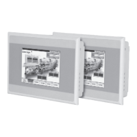
Positioned between the ELC graphics panels and the ePro series of operator interfaces, HM
i
is the work
horse of the industry. All units feature a touchscreen and function keys to suit all environments and
applications. They range in screen size and color to fit available space and application needs. All units
offer RS-232, RS-485 and RS-422 communications.
•
True analog touchscreen
•
Retentive internal data storage
•
Real time trending
•
Trend stored data
•
Alarming and alarm storage
•
Alarm frequency
•
Event storage (History)
•
USB programming
•
USB memory storage
•
USB printer
•
Add I/O
•
Macro programming
•
Multi-language
•
Recipe storage
•
Auto-scale application from 10 – 4"
•
On-line simulation
•
Off-line simulation
•
10 level password protection
Safety Information
Carefully note and observe the following safety precautions when receiving, inspecting, installing,
operating, maintaining and troubleshooting. The following words, WARNING AND CAUTION, are used to
mark safety precautions when using the Eaton product. Failure to observe these precautions may void
the warranty!
Installation
•
Comply with instructions for installation. Otherwise it may cause equipment damage.
•
Do not install the product in a location that is outside the stated specification for the device. Failure
to observe this caution may result in electric shock, fire or personal injury.
Wiring
•
Connect the ground terminals to a class-3 ground (ground resistance should not exceed 100Ω).
Improper grounding may result in electric shock or fire.
Operation
•
HM
i
users should use screen editor software to perform editing. Using HM
i
without the screen
editor software may result in abnormal operation.
•
Do not modify wiring during operation. Otherwise it may result in electric shock or personal injury.
•
Never use a hard or pointed object to hit or strike the screen as doing this may damage the screen,
causing HM
i
to work abnormally.
Maintenance and Inspection
•
Do not touch any internal or exposed parts of the device as electrical shock may result.
•
Do not remove operation panel while power is on. Otherwise electrical shock may result.
•
Wait at least 10 minutes after power has been removed before touching any terminals or
performing any wiring and/or inspection as an electrical charge with hazardous voltages may still
remain in the unit even after power has been removed.
•
Turn the power off before changing backup battery and check system settings after finishing the
change (all data will be cleared after changing the battery).
•
Be sure the ventilation holes are not obstructed during operation, or malfunction may result.
Wiring Method
•
Remove the terminal block from the HM
i
before wiring.
•
Insert only one wire into one terminal on the terminal block.
•
If the wiring is in error, perform the wiring again with proper tools. Never use force to remove the
terminals or wires, or malfunction or damage may result.
Communication Wiring
•
Comply with communication wiring specification for wiring.
•
Wiring length should comply with the stated specification for HM
i
.
•
Ensure proper grounding to avoid bad communication quality.
Available Communication Parts
2
COM1 Port
PIN
Contact
RS-232
1 N.C.
2 RXD
3 TXD
4 N.C.
5 GND
6 N.C.
7 RTS
8 CTS
9 N.C.
A Power input terminal
B Expansion slot
C Memory card
D COM 2
E COM 1
F USB
A Power input terminal
B Expansion slot
C Memory card
D COM 2
E COM 1
F USB
A Power input terminal
B Expansion slot
C Memory card
D COM 2
E COM 1
F USB
G Battery cover
COM2 Port
PIN
MODE 1 MODE 2
RS-422 RS-485
R- RXD- D-
R+ RXD+ D+
T- TXD- D-
T+ TXD+ D+
G GND GND
COM2 and COM3 Port
COMM
Port
PIN
MODE 1 MODE 2 MODE 3 MODE 4 MODE 5 MODE 6
RS-232 RS-422 RS-485 RS-232*2 RS-422*2 RS-485*2
COM2
1 N.C. RXD- D- N.C. RXD1- D1-
2 RXD RXD+ D+ RXD1 RXD1+ D1+
3 TXD TXD+ D+ TXD1 TXD1+ D1+
4 N.C. TXD- D- N.C. TXD1- D1-
5 GND GND GND GND GND GND
COM3
6 N.C. RTS- N.C. N.C. TXD2- D2-
7 RTS RTS+ N.C. TXD2 TXD2+ D2+
8 CTS CTS+ N.C. RXD2 RXD2+ D2+
9 N.C. CTS- N.C. N.C. RXD2- D2-
COM1 and COM3 Port
COMM
Port
PIN
MODE 1 MODE 2
RS-232 RS-422
COM1
1 N.C. N.C.
2 RXD RXD1
3 TXD TXD1
4 N.C. N.C.
5 GND GND
COM3
6 N.C. N.C.
7 RTS TXD2
8 CTS RXD2
9 N.C. N.C.
4" HM
i
6" HM
i
8" HM
i
10" HM
i
HM
i
Operator
Interfaces
Accessories (sold Separately)
The following accessories could help improve your HM
i
experience.
•
ELC-CBPCELCE — 3 meter cable to connect between the HM
i
and Eaton Logic Controller (ELC)
•
ELC-CBPCELC1 — 1 meter cable to connect between the HM
i
and Eaton Logic Controller (ELC)
•
HMIECPTR parallel printer expansion module
•
HMIEC0808 8 input and 8 output expansion module
•
HMIECENT Ethernet expansion card. Modbus TCP, upload and download
Unpack and Inspect
Included with the HM
i
are:
•
Panel Mounting clips (number of clips varies depending on the size of the unit).
•
DB9 gender changer for easy connection to the Eaton Logic Controller (ELC).
•
3-pin power 24V DC connector.
1
For 6", 8" and 10" HM
i
Only
8" HM
i
10" HM
i
6" HM
i
A Power input terminal
B COM 2
C COM 1
D USB