I.B. 2C12060H08
For more information visit: www.EatonElectrical.com
Instruction Book
Effective: May 2006
Page 48
Table 3.5 Undervoltage Release
Operational Dropout ① ➁
Opening
Control Voltage Range Volts Inrush/Continuous Time
Voltages 85-110% 30-60% Power Consumption (ms)
24 Vdc ①
32 Vdc ①
48 Vdc ①
110-125 Vdc ①
220-250 Vdc ①
110-127 Vac ➁
208-240 Vac ➁
380-415 Vac ➁
480 Vac ➁
600 Vac ➁
20-26 Vdc
27-35 Vdc
41-53 Vdc
94-138 Vdc
187-275 Vdc
94-140 Vac
177-264 Vac
323-457 Vac
408-528 Vac
510-660 Vac
7-14 Vdc
10-19 Vdc
14-29 Vdc
33-75 Vdc
66-150 Vdc
33-76 Vac
62-144 Vac
114-249 Vac
144-288 Vac
180-360 Vac
250 W/18 W
275 W/15 W
275 W/18 W
450 W/10 W
450 W/10 W
450 VA/10 VA
400 VA/10 VA
480 VA/10 VA
400 VA/10 VA
400 VA/10 VA
70
70
70
70
70
70
70
70
70
70
① Required for 200 ms
➁ Required for 400 ms
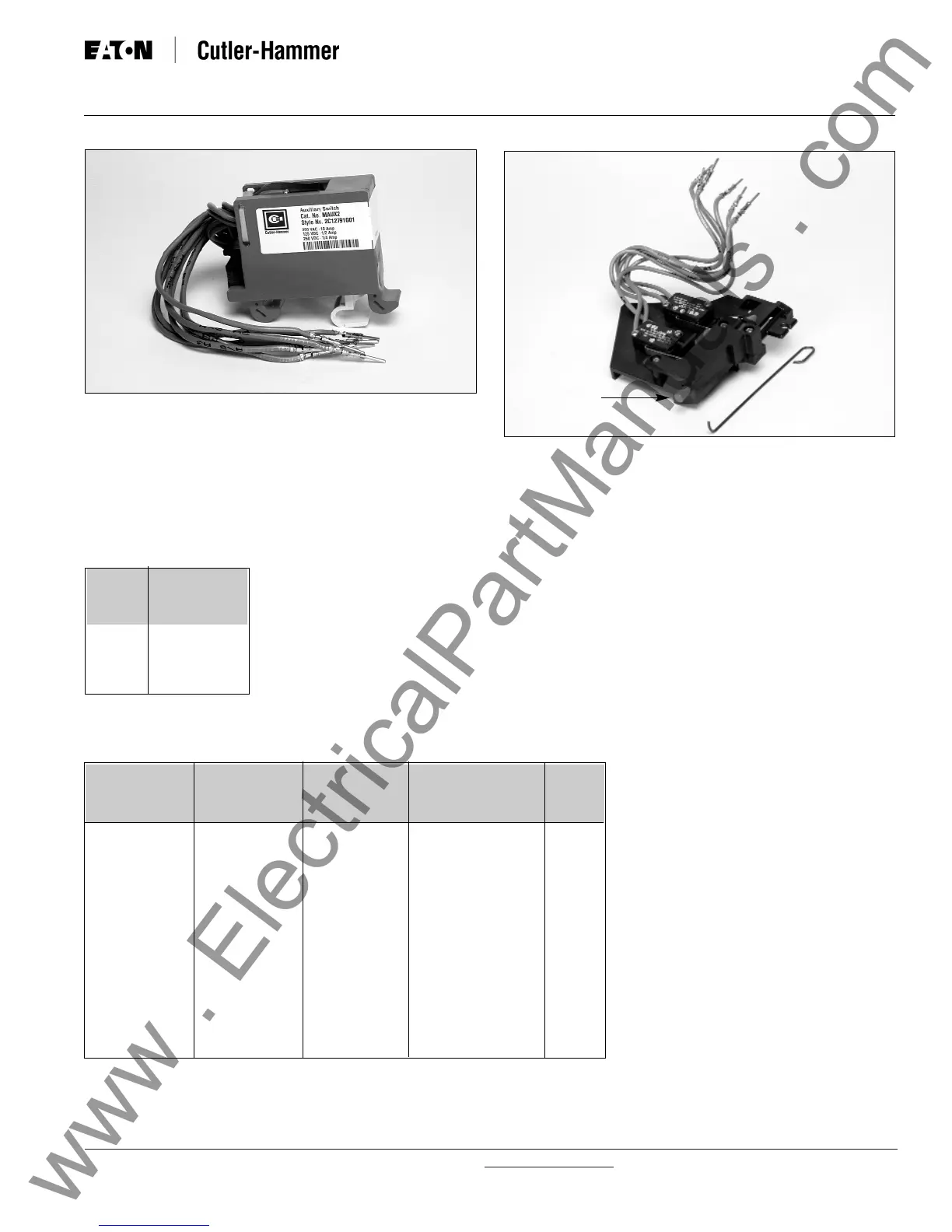
Figure 3-53 Auxiliary Switch (2A/2B)
Figure 3-54 Mechanical Trip Indicator with Associated
Overcurrent Trip Switch
Mechanical
Trip Indicator
Table 3.6 Auxiliary Switch,
Overcurrent Trip Switch and
Cell Switch Contact Ratings
Control Contact Rating
Voltages Inductive Load
(amperes)
250 Vac
125 Vdc
250 Vdc
10
0.5
0.25
3-8.2 INTERNAL ELECTRICAL ACCESSORIES
Other electrical accessories are mounted inside the cir-
cuit breaker. They can be factory or site installed.
There are two different internally mounted accessories:
• Overcurrent Trip Switch (Bell Alarm)
• Motor Operator
Overcurrent Trip Switch (Bell Alarm) - An overcurrent
trip switch (bell alarm) is an optional device (Figure 3-54).
It provides an electrical indication when a circuit
 Loading...