I.B. 2C12060H08
For more information visit: www.EatonElectrical.com
Instruction Book
Effective: May 2006
Page 23
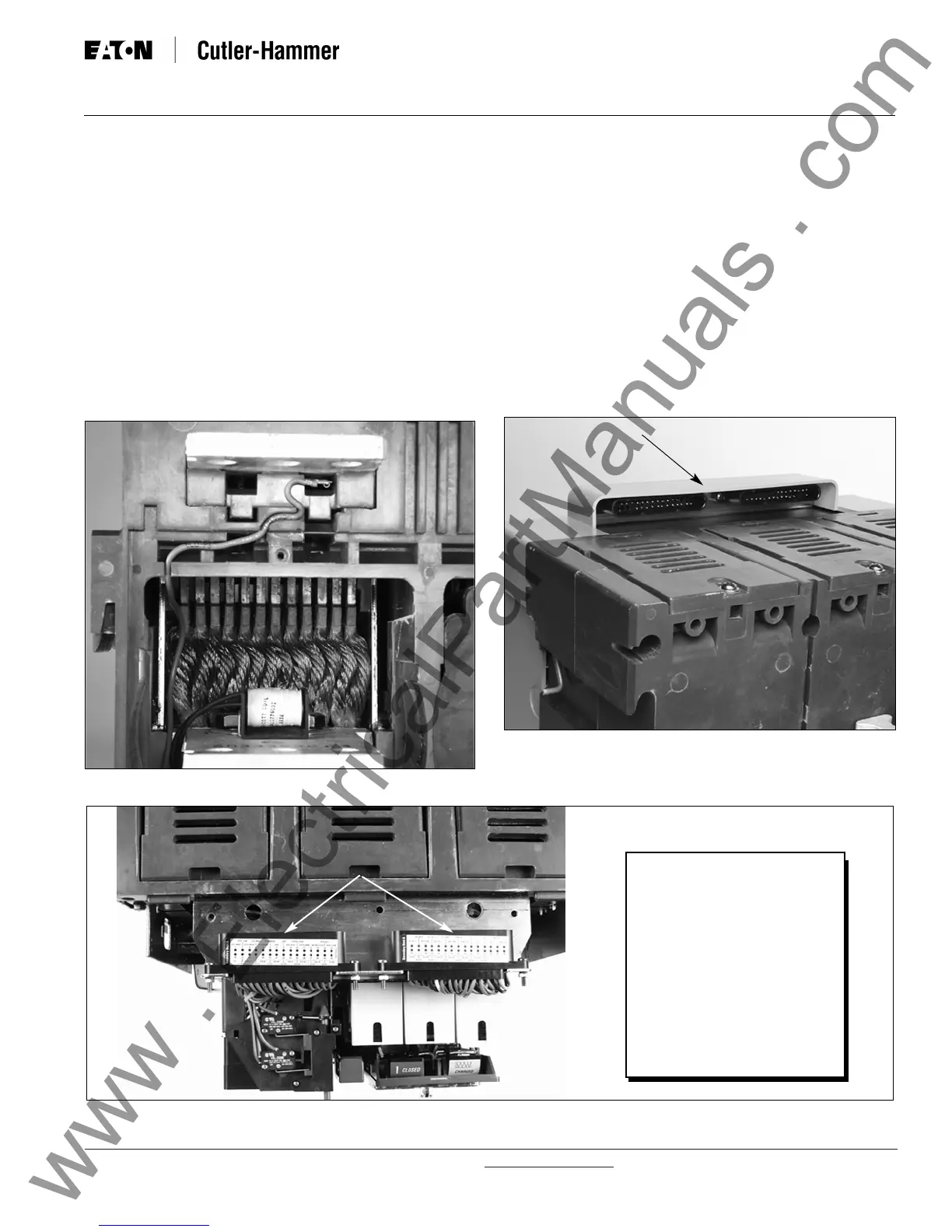
3-6.8 VOLTAGE TAPS
On circuit breakers with Digitrip 1150 trip units potential
taps are required to monitor the three phase voltages.
Voltage taps may be placed on either the line (top) or
load (bottom) terminals of the breaker at the factory.
Figure 3-21 illustrates line-side voltage taps.
3-7 SECONDARY CONTACTS AND CONNECTION
DIAGRAMS
A maximum of sixty secondary wiring connection points
are available on the standard frame circuit breaker (48
on narrow frame), each dedicated to a specific function
Figure 3-23 Secondary Connector Protective Hood
(Figure 3-22). The wiring points are finger safe with
no more than two wires per terminal.
Up to two secondary contact plug-in connectors (AMP),
each with 30 secondary points, are mounted on the top
rear portion of the circuit breaker . The plug-in connec-
tors are protected by a molded hood (Figure 3-23).
How many connectors are mounted depends upon a
number of considerations, such as whether the circuit
breaker is electrically or manually operated and how
many features are required. When the front cover of the
circuit breaker is removed, the top of each plug-in con-
nector is exposed. A label on each connector identifies
the wiring points.
Labels Legend
OTS Overcurrent Trip Switch
UVR Undervoltage Release
ATR Automatic Trip Relay
(520M and 1150 Trip
Units Only)
INCOM PowerNet
Communications Network
A BUS (Future Use)
A/S Auxiliary Contacts
NEUTRAL Neutral Sensor Input
GF SGND Source Ground Input
ZONE Zone Interlocking
ST Shunt Trip
SR Spring Release
MOTOR Charging Motor
LCS Latch Check Switch
Figure 3-22 Top View Secondary Connectors
Figure 3-21 Line-Side Voltage Tap for 1150 Trip Unit
Secondary Connector Labels
Protective Hood
 Loading...