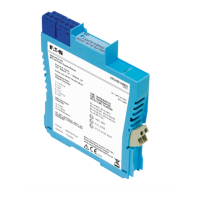
The MTL 9492-PS-PLUS is an intrinsically safe power supply module designed for use in hazardous areas, specifically for powering MTL 9460-ET series Ethernet modules. It is a key component in providing safe and reliable power within industrial environments where explosive atmospheres may be present.
Function Description:
The primary function of the MTL 9492-PS-PLUS is to convert a 24V DC safe area/Zone 2 supply into an intrinsically safe 12V DC nominal output. This intrinsically safe output is crucial for powering Ethernet modules located in Zone 1 hazardous areas, ensuring that no ignition source is created by the electrical supply. The module offers two distinct intrinsically safe outputs: an Ex ia IIB output and an Ex ib IIB output. The Ex ib IIB output provides a higher usable output power, which can be advantageous depending on the specific application and the gas group/zone requirements.
The module incorporates several features to enhance reliability and safety. It includes LED power indicators for both input and output, allowing for quick visual confirmation of operational status. Internal current limiting and electronic auto-reset circuit breaker action protect the module from short circuits or overloads. This protection mechanism minimizes power dissipation during fault conditions, contributing to improved system reliability.
Important Technical Specifications:
- Nominal IS Output:
- 12V 480mA 'ia' (Ex ia IIB output)
- 12V 550mA 'ib' (Ex ib IIB output)
- Supply Input: 24VDC (20-30V) 390mA
- Operating Temperature: -40°C to +70°C
- Storage Temperature: -40°C to +70°C
- Humidity: 5...95% RH, non-condensing
- Maximum Permissible Voltage (Um): 250V
- Approvals: ATEX, UKEX, and IECEx certified for various hazardous area classifications:
- [Ex ia Ma] I, [Ex ib Mb] I
- [Ex ia Ga] IIB, [Ex ib Gb] IIB
- [Ex ia Da] IIIC, [Ex ib Db] IIIC
- Ex nA IIB T4 Gc
- Mounting: DIN-rail or backplane mounting.
- Input Wire Size: Maximum permissible wire size for input power is 2.5mm² (14 AWG).
- Output Wire Size: Conductors should be between 14 and 24 AWG (1.6 and 0.5mm dia).
- Dimensions: Approximately 121.8mm (height) x 15.8mm (width) x 104.8mm (depth) for the module itself.
Usage Features:
- Isolated Power Supply: Provides electrical isolation between the safe area input and the hazardous area output, a fundamental requirement for intrinsic safety.
- Zone 2 Mountable: Can be mounted in a Zone 2 hazardous area, provided it is protected by a suitably certified enclosure with an ingress protection of IP54 minimum and suitable for operating temperatures of -40°C to +135°C.
- DIN-rail Installation: Modules can be easily clipped onto standard T35 DIN rails (7mm or 15mm high profile). A maximum mounting pitch of 16.2mm is recommended for each unit.
- Backplane Mounting: An alternative mounting method using standard MTL backplanes (e.g., CPS08) that can accommodate up to 8 modules with dual redundant 24V DC power supplies. This simplifies input power connections for multiple modules.
- Power Bus Option: A PB-8T power bus kit is available for DIN-rail installations, allowing up to 8 MTL 9492-PS-PLUS modules to be linked to a single 24V power supply, simplifying wiring.
- Power over Ethernet (PoEx) Adaptation: The module supports a simple adaptation of the IEEE 802.3af PoE standard to deliver power to 9400 Range hazardous area devices via Cat5e cable. This adaptation is necessary due to hazardous area restrictions and does not imply full 802.3af compliance.
- Removable Power Plugs: Both input and output power plugs are removable and fitted with screw clamp terminals, facilitating wiring and future maintenance. Plugs are mechanically keyed to ensure correct insertion.
- Tagging and Identification: Optional accessories like TH5000 tag holders and TAG57 tagging strips are available for individual module and backplane identification.
- Module Spacers: MS010 DIN rail module spacers (10mm) are available to provide adequate air circulation between modules when close-packed.
Maintenance Features:
- Module Removal: For DIN-rail mounting, modules can be removed by inserting a screwdriver into the clip and gently levering it outwards. For backplane mounting, a latch nearest the CE mark on the module label can be unclipped, allowing the module to be rotated and unplugged.
- Self-Resetting Protection: Internal current limiting and electronic auto-reset circuit breaker action mean that in the event of a short circuit or overload, the module will protect itself and automatically attempt to reset once the fault is cleared, reducing the need for manual intervention.
- No User Repair: The product is not designed for user repair. In case of damage or malfunction, it must be replaced with an equivalent certified product to maintain its explosion protection integrity.
- Clearance for Maintenance: Sufficient free cable should be allowed when wiring to permit easy removal of power plugs for future maintenance or replacement.
- Segregation of Wiring: Hazardous and safe-area wiring should be segregated into separate trunking or looms to prevent errors and maintain a tidy installation, which aids in troubleshooting and maintenance.
- Inspection and Maintenance Guidelines: Adherence to European, national, and local regulations (e.g., IEC 60079-17) for inspection and maintenance is required. Access to internal circuitry is not permitted during operation.