16
Instructional Booklet IB02102006E
Effective May 2011
Type MVS (previously WLI)
metal-enclosed switchgear—
4.76 kV, 15.0 kV, 27.0 kV, and 38.0 kV
EATON CORPORATION www.eaton.com
Operation
Mechanical safety interlocks
The MVS switch is equipped with switch interlocks and door inter-
locks, as well as provisions for padlocking in either the “Open” or the
“Closed” position.
WARNING
DEFEATING OR DISENGAGING SAFETy INTERLOCKS ON AN MVS SWITCH
THAT IS CONNECTED TO A POWER SOURCE MAy RESULT IN PROPERTy
DAMAGE, BODILy INJURy, OR DEATH.
DO NOT DEFEAT OR DISENGAGE ANy SAFETy INTERLOCKS.
Switch interlock
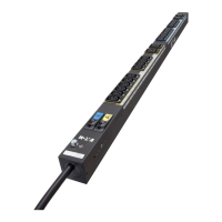
The switch interlock prevents inadvertent closure of the switch if the
enclosure door is open. When the door is closed, the pointed latch
lug welded to the inside of the door causes the safety latch to move
out of the blocking position (see Figure 21).
Figure 21. Door/Switch Mechanism and Shaft Interlock
Locations
Door interlock
The door interlock prevents the door of the enclosure from being
opened when the switch is “Closed.” When the switch is “Closed,” a
cam welded to the operating shaft engages a bracket welded to the
inside of the switch door, preventing the door from being opened
(see Figure 21).
Key interlocking
Key interlocks are supplied when specified. Certain MVS switchgear
configurations require key interlocks and they are therefore included.
Standard schemes are available for locking the switch in the “Open”
or the “Closed” position, as well as locking the main door closed.
Numerous other schemes are available for special requirements that
can coordinate with upstream or downstream devices supplied by
Eaton or other equipment.
Switch operation
The quick-make mechanism provides power to overcome blowout
forces that occur if the switch is “Closed” into a fault. However, these
forces are not transmitted to the operating handle because it is
not rigidly connected to the blades. Therefore, the switch can be
safely closed under short-circuit conditions within its fault-close rating.
Mechanism Cover
Door/Switch Shaft Interlock
Door/Switch Mechanism Interlock
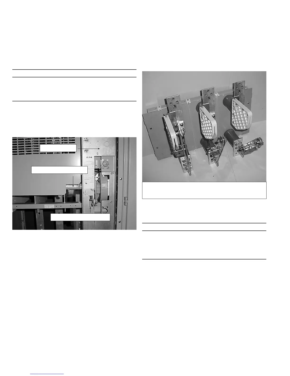
Load interruption is accomplished by a flicker blade and engaging
contact fingers located inside a DE-IONT arc chute. On opening the
switch, the main blades open first and all current is shunted through
the spring-loaded flicker blades. Further travel of the main blades
causes the flicker blades to snap out of their contact fingers where
associated arcing takes place within the arc chutes. See Figure 22
for the sequence of operation.
Figure 22. Main and Flicker Blade Operation
Fuse replacement
WARNING
WHEN ACCESSING FUSES, FAILURE TO ENSURE THAT THE FUSES ARE
DE-ENERGIzED MAy RESULT IN EQUIPMENT DAMAGE, BODILy INJURy,
OR DEATH.
MAKE SURE THAT ALL POWER SOURCES ARE DE-ENERGIzED BEFORE
ATTEMPTING TO ACCESS THE FUSES.
Step 1: All upstream devices that could energize the fuse should be
opened, padlocked, and tagged so that inadvertent closure cannot
create a hazard.
Step 2: The MVS switch should be in the “Open” position. This is
accomplished by rotating the operating handle downward.
Step 3: Before opening the door, look through a viewing window
to visually verify that all blades are disengaged from their break jaws.
Step 4: After opening the door, an appropriate medium voltage
sensing device should be used to determine if voltage is present.
Step 5: If no voltage is present, a suitable grounding device should
be attached to the fuse terminals to discharge any static charge and
ensure that the fuse terminals remain at ground potential.
Step 6: The fuses are removed by loosening the plastic hand
knobs and removing the locking bars. The fuses are then free to be
removed. When the fuses are re-installed, the hand knobs should be
retightened hand tight.
Left Pole: Main Blade and Flicker Blade Colsed.
Center Pole: Main Blade Open, Flicker Blade Closed.
Right Pole: Main Blade and Flicker Blade Open.

 Loading...