8
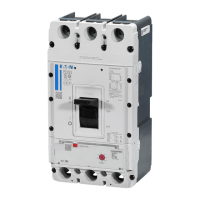
EATON CORPORATION www.eaton.com
Instructions for Undervoltage Release, Shunt Trip, and Overcurrent
Trip Switch
Instructional Leaflet IL0131087EN
Effective January 2019
Section 4: Installation of Overcurrent Trip in
Left Accessory Tray
Proceed with the following seven steps:
Step 1: If necessary, remove the front cover from the breaker by first
performing Steps 1 and 2 of Section 2.
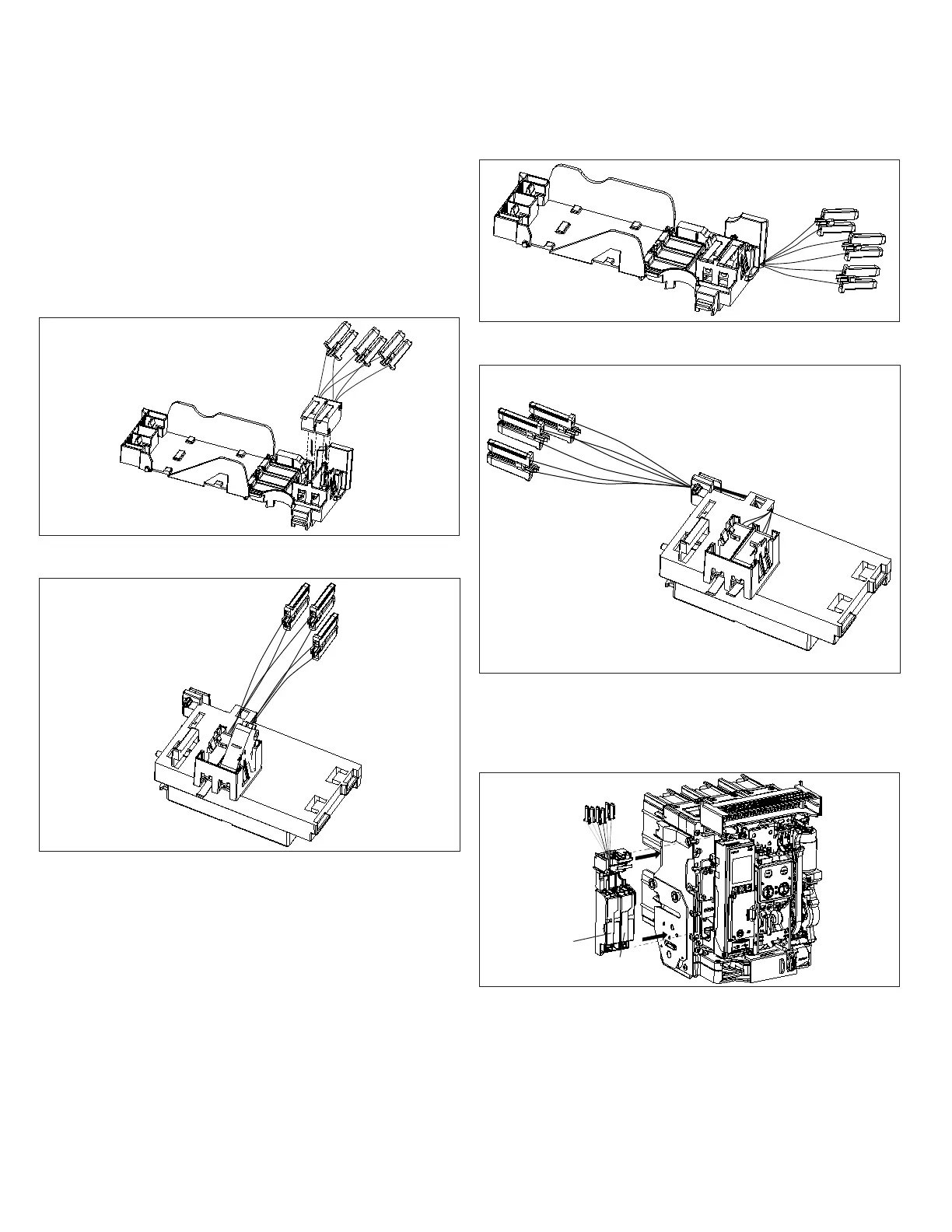
Step 2: Position the left accessory tray as shown and bring the two
OTS switches down for insertion into the left accessory tray. Carefully
push the OTS switches down until they lock in place.
Figure 24. Step 2 (NF Frame Shown).
Figure 25. Step 2 (RF Frame Shown).
ote:N For the RF Frame, the metal lever must pass through the opening
before locking switch in place.
Step 3: Route the six secondary leads and three connectors forward
and to the right out the end of the accessory tray for the NF Frame.
For the RF Frame, route the leads out as shown.
Figure 26. Step 3 (NF Frame Shown).
Figure 27. Step 3 (RF Frame Shown)
Step 4: Place the left accessory tray with the installed OTS switches
back in its original position as shown. Be careful not to bind secondary
wires or connector plugs.
Figure 28. Step 4 (NF Frame Shown).
ST
UVR
 Loading...