Replacing
Replacement draw lead type bushings can be installed by
following the removal procedure in reverse order. Clamp
bolts should be tightened as specified in Table 1.
The gasket under the bushing mounting flange and the
top gasket should be new or in good condition to ensure a
positive seal. The gasket mating surfaces must be clean and
smooth.
The threaded stud is keyed to the inside of the bushing to
prevent rotation while the terminal cap is being tightened. It
is important to have the threaded stud correctly seated. This
can be accomplished by pulling the stud up and turning it
until it is aligned and seated.
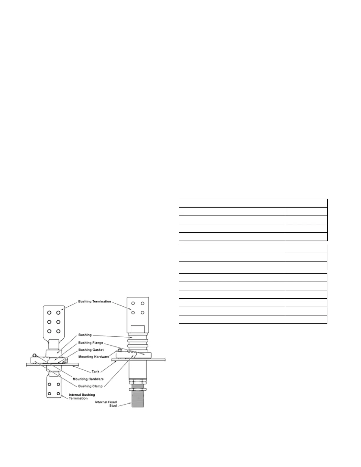
Removing and replacing fixed stud or spade type
bushings
Removing
1. Remove inspection cover (manhole) nearest to bushing,
only after all precautions outlined under "Removing and
Replacing Bushings" have been taken.
2. To remove the inspection cover:
A. Thoroughly clean the cover. Remove all dirt, grease
and moisture.
B. Release and remove cover bolts.
C. Remove the cover. Lift vertically to prevent damage
to bolt or cover gaskets.
3. Unbolt the connections–usually flexible straps–from the
bottom end of the bushing stud.
4. Remove the bushing mounting clamp nuts at the tank
to release the mounting clamp plate and free the
bushing for removal.
5. Remove the bushing.
Replacing
Replacement bushings can be installed by following the
removal procedure in reverse order. Clamp bolts should be
tightened as specified in Table 1.
The gasket under the bushing mounting flange should be
new or in good condition, and the gasket mating surfaces
must be clean and smooth.
After installing and connecting the new bushing, replace
the inspection opening cover, making certain the gasket is
in good condition and the gasket mating surfaces are clean
and smooth.
Return to the transformer any liquid removed and check for
the correct level.
A brief pressure test of the transformer at 5 psig to confirm
the integrity of the seals around all openings above the
liquid level is recommended. A solution of soap and water
will give indication of a leak by the presence of bubbles.
Bushing Clamps
4-hole Aluminum Cast Bushing Clamps 70-80 in.-lbs.
Molded Tri-Clamp Bushing 40-60 in.-lbs.
All other 3- & 4-hole Bushing Clamps 40-60 in.-lbs.
2-hole Bushing Clamps 55-65 in.-lbs.
TABLE 1 Torque Values
Internal Spade Bushings
1/2" Steel (Grade 8) 50 ft.-lbs.
3/8" Steel (Grade 8) 50 ft.-lbs.
Internal Stud Bushings
3/8"-16 Brass Nuts 16 ft.-lbs.
5/8"-11 Aluminum Nuts 60 ft.-lbs.
5/8"-11 Brass Nuts 75 ft.-lbs.
1"-14 Brass Nuts 121 ft.-lbs.
Bushing Lead Block, ½” Steel Hardware 110 ft.-lbs.
Figure 12. Fixed stud and spade type bushings.
12 SubStation tranSformer inStallation and partS replacement information MN202002EN JUNE 2016
 Loading...


