This manual describes the overhaul procedures for Vickers Quiet Intra-Vane Type Double Pumps, specifically the 2520V, 3520V, 3525V, 4520V, 4525V, and 4535V Series with -20 Design 282/283 Suffix. These pumps are designed to operate at reduced noise levels while maintaining the reliability, operating characteristics, and service advantages of previous models.
Function Description:
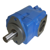
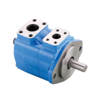
The Vickers Quiet Intra-Vane Type Double Pumps are fixed and variable delivery inline piston type pumps and motors. Their primary function is to provide hydraulic power by converting mechanical energy into hydraulic energy. The pumps utilize a balanced intra-vane design, where a slotted rotor, splined to the drive shaft, turns inside a cam ring. Vanes fitted into the rotor slots follow the inner surface of the cam ring as the rotor turns, forming pumping chambers between the vanes, cam ring, and two end plates. Centrifugal force and pressure under the vanes hold them against the cam ring. Outlet pressure is continuously applied to the small intra-vane area of the vane. As the pump vane rotates through high and low quadrants, outlet pressure is alternately applied to the rest of the under-vane area. This varying pressure under the vane reduces wear and increases pump efficiency. Pump delivery can be adjusted by changing the ring or installing a new cartridge kit.
Important Technical Specifications:
The manual provides a model code breakdown for various configurations, including special seals for mineral and fire-resistant fluids, different pump series (2520, 3520, 3525, 4520, 4525, 4535), and SAE delivery USgpm ratings for both shaft and cover ends. For example, shaft end delivery ranges from 12-21 USgpm for 2520V models to 42-60 USgpm for 4520V, 4525V, and 4535V models. Cover end delivery ranges from 2-14 USgpm for 2520V, 3520V, and 4520V models to 25-38 USgpm for 3525V, 4525V, and 4535V models. Shaft types include straight with square key (standard) and straight with square key (heavy duty for all models except 2520V). The pumps are available with different port connections (SAE 4 bolt flange or SAE straight thread at #2 outlet port) and mounting options (SAE 2 bolt or foot mounting). Shaft rotation can be left-hand (L) or right-hand (Omit) when viewed from the shaft end.
Minimum allowable ring/rotor clearance specifications are provided for different models, ranging from 0.0007 inches for 20V models to 0.0016 inches for 45V models. Torque specifications for screws (18) vary by model: 48-55 N.m (65-75 lb.ft.) for 2520V, 102-118 N.m (140-160 lb.ft.) for 3520V and 3525V, and 188-203 N.m (255-275 lb.ft.) for 4520V and 4525V. Torque specifications for screws (4) are: 54-68 N.m (40-50 lb.ft.) for 2520V, 3520V, and 4520V; 88-102 N.m (65-75 lb.ft.) for 3525V and 4525V; and 188-203 N.m (255-275 lb.ft.) for 4535V.
Usage Features:
These pumps are designed for direct mounting, with a pilot on the pump mounting flange ensuring correct alignment. Indirect drive is not recommended without Vickers engineering approval. Proper shaft rotation (clockwise for right-hand, counter-clockwise for left-hand) is critical to prevent seizure. The manual emphasizes the importance of clean hydraulic fluid, recommending thorough cleaning of new systems, continuous filtration, and protection from airborne contamination. Fluid selection should be made with the assistance of a reputable supplier, with data sheet 1-286 providing detailed recommendations. Sound levels can be affected by fluid conditions such as high viscosity at low temperatures (causing cavitation), entrained air, or aerated fluid from leaks. Overload protection is achieved through a relief valve that limits system pressure. During start-up, a minimum drive speed of 600 RPM is recommended for priming, and the pump housing should be filled with fluid. Air trapped in the system may need to be purged by cracking a fitting on the outlet side.
Maintenance Features:
Regular maintenance is crucial for optimal performance and longevity. This includes periodic inspection of fluid condition and tube/pipe connections to prevent leaks and ensure proper operation. The reservoir should be checked for contaminants, and the system drained and cleaned if contaminated. Filter elements must be checked and replaced periodically to prevent pressure drops and contamination bypass. Air bubbles in the reservoir should be identified and sealed. Excessive noise or overheating indicates potential failure, requiring immediate shutdown and correction. When adding fluid, it must be poured through a clean wire screen (200 mesh or finer) or a 10-micron filter to prevent contamination. Internal lubrication is provided by the system fluid, while shaft coupling lubrication should follow manufacturer specifications. Shaft splines should be coated with a dry lubricant (e.g., Molycoat) to prevent wear.
For overhaul, only genuine Vickers parts should be used, as sophisticated design processes and materials are used in their manufacture. Repair kits, which include commonly replaced parts, are recommended for complete overhaul. Individual cartridge parts are not interchangeable with similar parts of previous design models, but complete cartridge kits are interchangeable with previous designs. The overhaul process involves unit removal, thorough cleaning, disassembly, inspection, repair, and reassembly. Special tools, such as a shaft seal driver, may be required. During disassembly, components like seals, cartridge kits, and the shaft group are removed. Inspection involves checking internal passages for cleanliness, mating surfaces for nicks and burrs, locating pins, threaded parts, snap ring recesses, and bearing condition. Ring/rotor clearance should be measured with a dial indicator. During assembly, new seals should always be used, and components should be lubricated with hydraulic fluid. Critical steps include positioning the seal with the garter spring inward, pressing the bearing onto the shaft, and ensuring correct orientation of rotor arrows and vane sharp edges in the direction of pump rotation. After reassembly, the unit should be tested according to recommended speeds and pressures, with the drive shaft properly aligned and all connections tight.