Home
Ebyte
Wireless modules
E18 Series
Ebyte E18 Series User Manual
5
of 1
of 1 rating
16 pages
Give review
Manual
Specs
To Next Page
To Next Page
To Previous Page
To Previous Page
Loading...
Chengdu
Ebyte
Electronic
T
echnology
Co.,ltd.
E18-MS1PA
2-PCB
User
Manual
Copyright
©2012
–2019
,
Chengdu
Ebyte
Electroni
c
T
ec
hnology
Co.,Ltd.
2-5
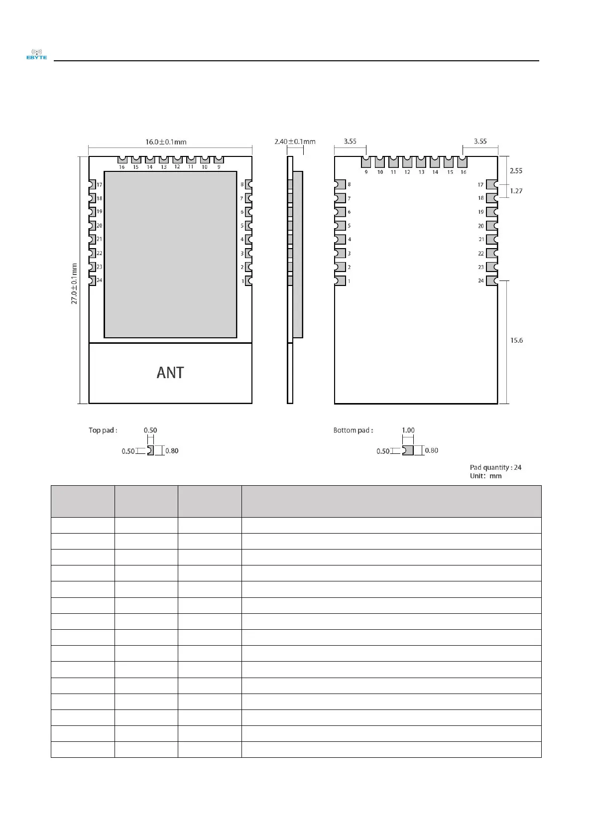
3.
Size
and
pin
definiti
on
Pin
No.
Pin
item
Pin
direction
Application
1
GND
Input
Ground,
c
onnecting
to
power
supply
reference
gro
und
2
VCC
Input
Power
sup
ply,
must
be
2.0-3.6V
3
P2.2
Input
/Ou
tput
MCU
GPIO
4
P2.1
Input
/Ou
tput
MCU
GPIO
5
P2.0
Input
/Ou
tput
MCU
GPIO
6
P1.7
Input
/Ou
tput
MCU
GPIO
7
P1.6
Input
/Ou
tput
MCU
GPIO
8
NC
N.C.
9
NC
N.C.
10
P1.5
Input
/Ou
tput
MCU
GPIO
11
P1.4
Input
/Ou
tput
MCU
GPIO
12
P1.3
Input
/Ou
tput
MCU
GPIO
13
P1.2
Input
/Ou
tput
MCU
GPIO
14
P1.1
Output
MCU
GPIO
,
PA
transmission
control
pin
15
P1.0
Output
MCU
GPIO
,
PA
receiving
con
trol
pi
n
5
7
Table of Contents
Table of Contents
2
General Introduction
3
Brief Introduction
3
Features
3
Application
4
Specification and Parameter
4
Limit Parameter
4
Operating Parameter
4
Size and Pin Definition
6
Usage
7
Programming
8
TI Zigbee FAQ
8
Basic Operation
11
Hardware Design
11
Faq
12
Communication Distance Is too Short
12
Module Is Easy to Damage
13
Ber(Bit Error Rate) Is High
13
Welding Instruction
13
Reflow Soldering Temperature
13
Reflow Soldering Curve
14
E18 Series
14
Antenna Recommendation
15
Other manuals for Ebyte E18 Series
Operation Instructions
6 pages
5
Based on 1 rating
Ask a question
Give review
Questions and Answers:
Need help?
Do you have a question about the Ebyte E18 Series and is the answer not in the manual?
Ask a question
Ebyte E18 Series Specifications
General
Brand
Ebyte
Model
E18 Series
Category
Wireless modules
Language
English
Related product manuals
Ebyte E180-Z6907A
41 pages
Ebyte E01 Series
19 pages
Ebyte E32 Series
24 pages
Ebyte E32-TTL-1W
24 pages
Ebyte E32-433T30S
24 pages
Ebyte E32-900T20D
22 pages
Ebyte E32-433T30D
37 pages
Ebyte E22-900T22S
37 pages
Ebyte E22-230T22S
37 pages
Ebyte E220-400T22D
23 pages
Ebyte E32-433T20S1
24 pages
Ebyte E22 T30D Series
37 pages
 Loading...