PROSWEEP ATTACHMENT
OPERATOR'S MANUAL
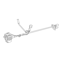
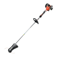
9
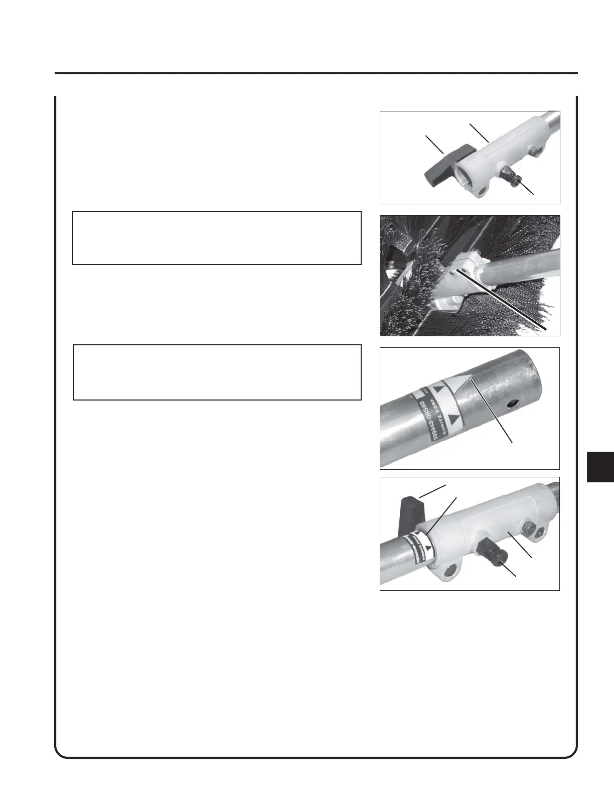
A
B
D
C
F
D
B
E
A
POWER HEAD SHAFT/LOWER SHAFT ASSEMBLY
1. Set Power Head/Shaft Assembly on a level surface.
2. Pull locator pin (A) out, and turn counter-clockwise 1/4 turn to lock-
out position.
3. Remove vinyl cap from attachment drive shaft.
CAUTION
Thrown objects hazard. Install lower drive shaft so that gear
housing mounting bolts (E) face upwards. Otherwise debris will be
thrown toward user.
4. Remove cardboard spacer from coupler, if necessary.
5. Carefully fit attachment drive shaft assembly into coupler (B) to
decal assembly line (C), making sure that the inner lower drive shaft
engages upper drive shaft mount.
NOTE
Earlier model Power Heads may have shorter couplings. Short
couplings fit flush to decal point (F). New couplings are 4-3/4 in.
long, and fit flush to line (C).
6. Rotate locator pin (A) 1/4 turn clockwise to engage lower shaft
hole. Insure locator pin is fully engaged by twisting lower drive
shaft. Locator pin should snap flush in coupler. Full engagement will
prevent further shaft rotation.
7. Secure lower shaft assembly to coupler by tightening clamping
knob (D).
 Loading...