2
1. General information EN
For safety reasons it is important to read all of the enclosed information
(Installation guide, Service manual, Spare parts, Operating instructions)
before mounting this equipment.. In addition, the legislation in force at the
time of purchase must always be considered in connection with the installa-
tion and mounting of this equipment, no matter the contents of this manual.
If there are matters of dispute please contact your dealer.
This equipment is produced and tested by specially qualied personnel,
following approved instructions to ensure our high level of product qual-
ity. After the product is nished and tested it is manually inspected with the
ultimate test carried out just before the product is released for shipping. To
obtain our high level of quality and long life we use stainless steel parts.
These parts, in deance of our manual inspections may still have some
sharp edges, which can present a cut hazard. Therefore it is advised always
to use protective gloves and show caution when installing the equipment.
2. Preparation Wall / Floor
If the wall is made of bricks or concrete, the enclosed screws and rawl plugs are
usable, otherwise you have to make sure that the carrying
capacity of the wall is sufcient.
Note: The pipeline must be rinsed through before the system is
connected. See service manual.
Note: Remove cover before the system is mounted on the wall.
Note: The weight of the unit are listed in the Service manual under the
section "Specications"
3. Placing/application
• Do not use the machine outdoors.
• Main station must be placed in frost free rooms only.
• Free space around the main station: min 1500 mm.
• Max. ambient temp. 40°C.
• Non vibrating surface.
4. Water supply
BW3 BW4 BW7
Water volume 100 l/min. 135 l/min 265 l/min
Pressure 0,2 - 0,8 MPa
(2 - 8 bar)
0,2 - 0,8 MPa
(2 - 8 bar)
0,2 - 0,8 MPa
(2 - 8 bar)
Max. temperature 70
o
C 70
o
C 70
o
C
BF3 BF4 BF8
Water volume 100 l/min. 135 l/min 265 l/min
Pressure 0,2 - 0,8 MPa
(2 - 8 bar)
0,2 - 0,8 MPa
(2 - 8 bar)
0,2 - 0,8 MPa
(2 - 8 bar)
Max. temperature 70
o
C 70
o
C 70
o
C
The supply line must be sized so that it can supply the minimum indicated pres-
sure and water volume when connected to this equipment. When dimensioning
the water supply, it is recommended to increase the available volume with 15-20
% compared to the minimum requirements listed in the table.
Note: It is recommended to mount a mixing system on the water
connection immediately before the outlet which is used.
Recomented water hardness 14-18 dH°. The equipment will
operate with water hardness exciding this level however, de
scaling of pump system, injectors and like must be
expected depending on use pattern and water quality.
Furthermore, wear of the mechanical parts will increase as well.
If not supplied, lter should be mounted.
5. Power supply
Connection instruction is mounted on the cables.
The phase order is subordinated.
Earth Leakage Circuit Breaker (ELCB).
When using an earth leakage circuit breaker (ELCB) also known as a residual
current device (RCD) or a residual current circuit breaker (RCCB) in a system
that incorporates a variable speed drive connected to 3 phase 400 V.
The trip level of the ELCB has to be 300 mA.
(30 mA used in house hold will malfunction due to earth leakage)
Service Switch:
The unit must always be connected to the main supply through a separate
service switch.
NB! Installation must always be in accordence with local legistration.
BW3 BW4 BW7
Voltage: 3/PE 400 Vac
±10%
3/PE 400 Vac
±10%
3/PE 400 Vac
±10%
Fre
quenz:
50/60 Hz
48 -0%…62 +0%
50/60 Hz
48 -0%…62 +0%
50/60 Hz
48 -0%…62 +0%
Motor load: 4 kW 5.5 kW 10 kW
Nominal current: 10.6 A 14.2 A 27 A
Fuse: 16 A 20 A 35 A
L1, L2, L3, PE 2.5 mm
2
2.5 mm
2
6 mm
2
BF3 BF4 BF8
Voltage: 3/PE 400 Vac
±10%
3/PE 400 Vac
±10%
3/PE 400 Vac
±10%
Fre
quenz:
50/60 Hz
48 -0%…62 +0%
50/60 Hz
48 -0%…62 +0%
50/60 Hz
48 -0%…62 +0%
Motor load: 4 kW 5.5 kW 11 kW
Nominal current: 10.6 A 14.2 A 27 A
Fuse: 16 A 20 A 35 A
L1, L2, L3, PE 2.5 mm
2
2.5 mm
2
6 mm
2
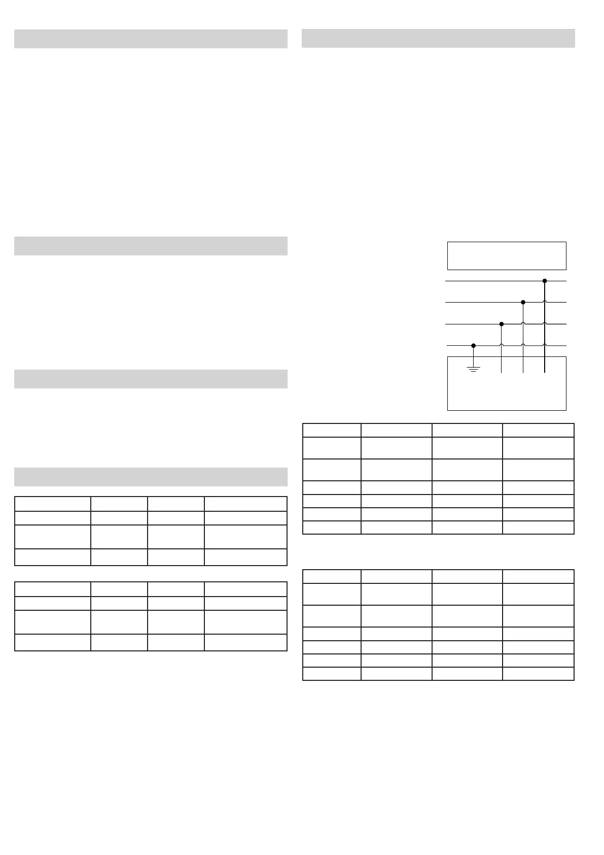
Mains
3/PE 400 Vac ± 10%
48 Hz ... 62 Hz
Green/Yellow L3 L2 L1
Note: Phase sequence unimportant.
Connecting cable.
L1
L2
L3
PE
 Loading...