9
English
Hardware Installation Guide
Installation Steps
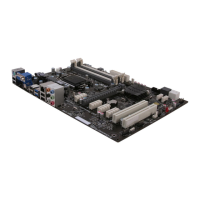
Step 3. Installation of an Expansion card:
Remove the metal located on the slot and then insert the expansion card into the
slot. Press the card firmly to make sure it is fully inserted into its slot. And then
return the screw back to its position.
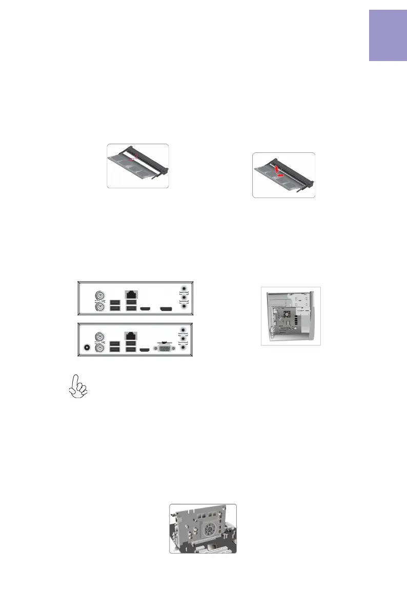
Step 1. Installation of Memory Modules:
1-1. Align the cutouts on the DIMM
module edge connector to the notches
in the DIMM slot.
Step 2. Installation of Motherboard:
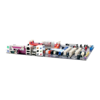
2-1. Replace the back I/O plate of the
case with the I/O shield provided in
motherboard’s package.
1-2. Insert the memory module to the
slot and press it down until it seats
correctly. Make sure the slot latches
cling to the edge of the DIMM module.
2-2. Place the motherboard within the
case by positioning it into the I/O plate.
Secure the motherboard to the case
with screws.
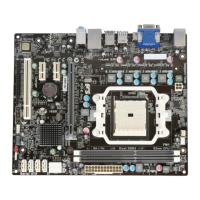
VGA port(real panel I/O) + DC_IN port(real panel I/O) and DP port (real panel
I/O) + ATX_POWER header(internal I/O header) are alternative options of
the motherboard.
 Loading...