Caution: To prevent damage when attaching the feet
to the heater, place the heater upside down on a soft
surface (e.g. a carpet).
When attaching the feet, make sure that they are
positioned on the correct sides of the equipment
(notch facing inwards) and are fastened with 4
screws (A).
b) Wall mounting (Fig. 3)
Caution: Make sure that there are no electric cables
or other installations (for example water pipes) near
the drill holes. Ensure that the equipment is secured
firmly and horizontally to the wall. Use only suitable
fastening material on a suitably stable wall. The
supplied dowels and screws are suitable for the
following: Concrete, natural stone with a dense
structure, solid brick, solid limestone bricks, solid
lightweight concrete bricks and aerated concrete.
Ensure that a minimum distance of 230 mm to the
sides and 650 mm to the top of the equipment are
maintained. The mounting height (upper edge of the
heater) must be less than 180 cm.
Observe point 1 - Safety information.
앬 Do not attach the feet if the equipment is to be
mounted on the wall.
앬 When selecting the location for the appliance,
please note that if there are skirtings on the floor,
the minimum distance to the housing, or the
installation height, has to be measured from the
top of the skirting.
앬 Then drill the two fastening holes with 6 mm
diameter. The centres of the holes must be
marked so that they are 416 mm apart and
horizontal (3) and at least 580 mm above the
floor (allow for skirtings) and the holes must be
drilled accordingly.
앬 One left and one right bracket are screwed to the
wall.
앬 Use two short screws to mount the remaining
brackets to the bottom of the convector heater in
place of the feet. They will act as spacers
between the equipment and the wall.
앬 Hang the convector heater on the wall and hang
the fixing brackets in the slots.
7. Operation
Caution: Before using the equipment for the first
time, check that the voltage supply is the same as
the voltage details set out on the rating plate.
Read the safety regulations in section 1.
When the equipment is used for the first time or after
a long period of rest it may emit an odour for a short
time. This is not a fault.
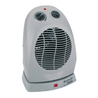
7.1 Heat output switches (Fig. 1):
앬 Low heat output – activate switch (Item 6)
앬 Medium heat output – activate switch (Item 7 )
앬 Maximum heat output – activate switch (Item 6)
and (Item 7)
7.2 Thermostat controller/Room temperature
regulator (Fig. 1/Item 3):
Switch on the required heat output using the two
function switches. Turn the control to “MAX” until the
required room temperature has been reached. Then
turn down the control until you hear a clear click. The
thermostat control will switch the radiator on and off
automatically to maintain the room temperature at an
almost constant level. However, this presupposes
that the radiator has sufficient output to cover the
heating requirements for the room.
Note: “MIN” setting = antifreeze setting (ca. 5°C)
7.3 Ventilator switch (only CH 2000/1 TT)
(Fig. 1/ Item 5)
Switch ventilator ON/OFF (Fig. 1/Item 4)
Note: The ventilator only works if the thermostat
controller is switched on, i.e. the temperature set on
the thermostat controller is higher than the actual
room temperature. The ventilator can be used with
heat output (heating fan) or without heat output
(cooling fan). Objects must be kept at a distance of
at least 1 metre from the air outlet.
7.4 Time switch (only CH 2000/1 TT) (Fig. 1/Item
2)
The time switch only runs as long as the convector is
connected to the mains. The convector is switched
on using the switch integrated in the time switch. The
switch positions have the following meanings:
Position “I” = Convector can only be switched ON or
OFF manually.
Position “Clock Symbol” = Automatic operation:
Convector is switched ON or OFF automatically.
13
GB
 Loading...