entilation grilles
he openings in the caravan wall must be fitted with the
lectrolux Ventilation systems.
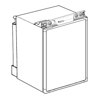
itting the grilles, model A 1620, fig.2, which were speci-
lly developed by Electrolux for this purpose. It is a good
dea to install the frame R 1640 (B in fig. 7a) at the same
ime. Then the grilles can be easily removed, which permits
nspection and small repairs to be carried out without the
ecessity for removing the refrigerator from the recess.
f there is no outer grille at floor level where leaking gas can
scape, a 40 mm hole to the outside should be made in the
loor of the recess to drain any unburnt gas to the outside.
it the hole with wire mesh and an angled plate to protect
rom stones, mud etc.
emoval of flue gases
he ventilation passage at the rear of the recess, between
he outer wall of the vehicle and the refrigerator (fig. 7a/b),
s sealed off against the living space, and so cold draughts
re excluded (winter camping) and no flue gases can
enetrate into the vehicle. Thus a special flue outlet is no
onger necessary – the gases are dispersed through the
pper vent grille.
ote: With this mode of installation the same type of grilles
without an integrated flue outlet), should be installed at the
pper as well as at the lower vent opening. The angled
-piece for the flue tube (when delivered) should not be
sed in this case.
he top of the enclosure above the flue tube (I), fig. 7a/b,
hould be covered with aluminum sheet metal, as indicated
n (B), to facilitate the heat dispersion.
n fig. 7 the letters have the following meaning:
A. Frame R 1640 for the grilles
B. Aluminum cladding
C. Condenser of cooling unit
D. Vent grill A 1620
E. Sealing profile (optional extra)
Width:
525 mm, part. nr. 295 1147-00
486 mm 295 1147-10
F. Refrigerator rear wall
G. Wooden batten 10 x 20 mm (see also fig. 5)
H. Height of the enclosure
(see TECHNICAL DATA)
I. Flue tube
K T-piece ("lazy tee")
P GAS CONNECTION
he refrigerator is designed for operation on LP gas, the
ressure of which must be 28 mbar for Butane and 37 mbar
or Propane. Check that this is stated on the data plate.
he refrigerator is not designed for operation on town gas
r natural gas.
he gas installation should only be carried out by an autho-
ized gas fitter. It is recommended that the gas pipe feeding
he refrigerator is so arranged that it is possible to turn off
he supply of the refrigerator. It must be of a type approved
or use with continuously operating bottled-gas appliances,
nd have threaded compression connections throughout.
USH-ON CONNECTIONS MUST NOT BE USED (We do
ot approve the use of "rubber" type flexible tubing for
onnecting permanently operating appliances of this type in
he United Kingdom). All connectors etc. should be of a type
pecifically designed for the type and diameter of the con-
ection pipe used, and screwed joints should be sealed with
joining compound approved for use with bottled gas.
he gas supply pipe should be connected to the gas inlet
ipe on the right hand side of the gas control valve by
eans of a suitable threaded compression coupling.
n making the connection to the refrigerator, a gas cock of
n approved type for use on LPG must be incorporated in
he supply line in a position which is readily accessible to
he user. For eventual servicing purposes, the union should
e on the outlet side of the cock and the pipework should
e positioned so as not to prevent the refrigerator from
eing readily withdrawn.
LECTRICAL CONNECTION
he electrical installation must be carried out in a proper
nd durable manner, taking into account all relevant regula-
ions and codes of practice. For mains voltage operation, it
s important that the circuit to and in the caravan is effec-
ively earthed. ALL MAINS VOLTAGE WIRING IN THE
ARAVAN MUST BE INSTALLED IN ACCORDANCE
ITH CURRENT I.E.E. REGULATIONS INCLUDING THE
SE OF AN OUTLET AND COUPLER TO BS4343/-
EE17.
or connection to a 230 V electricity supply, the refrigerator
as a 3-core mains lead which is intended for connection to
properly earthed plug and socket outlet. The socket outlet
hould be fitted in the caravan in a position readily accessi-
le to the user, within reach of the mains lead. In the United
ingdom, the plug and socket outlet should be of the non-
eversible type.
MPORTANT: The wires in the mains lead of this appliance
re coloured in accordance with the following code:
REEN-AND-YELLOW = EARTH
LUE = NEUTRAL
ROWN = LIVE
s the colours of the wires may not correspond with the
oloured markings identifying the terminals in your plug, in
he United Kingdom, proceed as follows:
he wire which is coloured GREEN-AND-YELLOW must be
onnected to the terminal in the plug which is marked with
he letter E or by the earth symbol or coloured green or
reen-and-yellow.
he wire which is coloured BLUE must be connected to the
erminal which is marked with the letter N or coloured black.
he wire which is coloured BROWN must be connected to
he terminal which is marked with the letter L or coloured
ed.
11
 Loading...