5
www.eltherm.com
5
www.eltherm.com
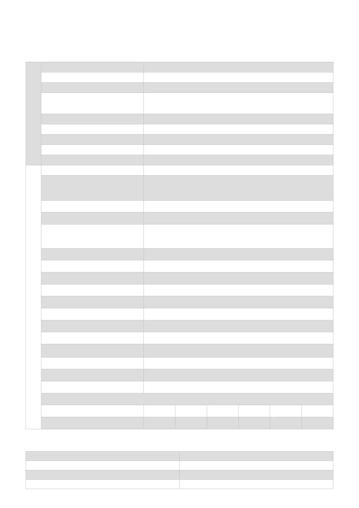
TECHNICAL DATA
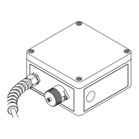
HOUSING / MOUNTING STAND
Material Polyamide, non-conductive, UV-resistant
IP protection type IP 65
Cable entries for mounting base 1x at, 1x round
Line dimensions
Ø 3-5 mm (sensor)
4.0x11 mm - 5.5x14 mm (heating cable - suitable for ELSR-H, -LS,-N, -SH, -SHH)
Permitted jacket materials TPE min. 0.7 mm; uoropolymer min. 0.4 mm
Max. width of strap 16 mm
Possible pipe diameters ≥ 20 mm
Interference immunity min. 7J
Ground approx. 1.5 kg
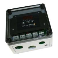
CONTROLLER
Nominal voltage 230 ± 10% V AC, 50 Hz
Nominal load
Single pole
Max. 25 A (+ 40 °C) T6 with connecting line >= 2.5 mm²
Max. 20 A (+ 50 °C) T6 with connecting line >= 2.5 mm²
External fuse protection 25 A (20 A)
Power consumption approx. 5 VA without load
Sensor connection
Intrinsically safe 2-wire connection (jumper required between terminals 2 and
3) or
3-wire connection with automatic conductor compensation up to max. 20
Relay output for collective alarm (not /M) 1 N/O contact 3 A, 250 VAC, 100 VA or 5 A, 24 VDC, 100 W
MODBUS (/M only) RS485 RTU (max. 120 devices), Um = 6Vmax
Temperature unit °C
Measuring range -99 ... 450 °C
Setpoint range 1 ... 450 °C (T1), factory setting: 5 °C
Undertemperature alarm (not /L) 1 ... 450 °C, factory setting: 0 °C
Overtemperature alarm (/AL only) 1 ... 450 °C, factory setting: 0 °C
Switching accuracy <2 K
Hysteresis
<100 °C: 3 K
>100 °C: 3 %
Setpoint setting One rotary knob each for hundreds, tens and ones place (0...9)
Connection cross-sections 0.2 ... 4 mm²
Terminal tightening torque 0.6 ... 0.8 Nm
Intrinsically safe measuring circuit (maximum values) U=2.5V, I=36.8mA, P=40mW, R=155 ohms
Max. capacitance 44 mH 10 mH 1 mH 100 mH 10 mH 1 mH
Max. inductance 1.2 F 7.1 F 14 F 28 F 65 F 110 F
Adapter -20°C up to +100°C
Mounting base -20°C up to +200°C
Housing (depending on screw connection) -45°C up to +50°C
Controller (depending on load) -55 °C to +40 °C / +50 °C
OPERATING TEMPERATURE
 Loading...