2
© 2011 Emerson Climate Technologies
Printed in the U.S.A.
AE5-1377 R2
Application Engineering
BULLETIN
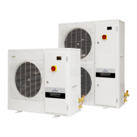
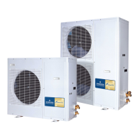
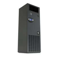
Introduction
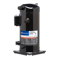
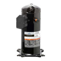
Copeland Scroll
®
outdoor condensing units provide the
many benefi ts of scroll compressor technology, coupled
with advanced diagnostic controls, to ensure reliable
performance and operation in foodservice applications.
Electronics are used extensively in its protection and
diagnostic features. These features are controlled by an
electronic integrated control board. The control board
provides base control functions related to temperature
controller, defrost, evaporator fan control, compressor
protection e.g. current overload, phase reversal, liquid/
vapor injection control, self diagnostics and warnings.
These error codes can be seen by an LED display for
easy and rapid troubleshooting and maintenance.
A complete product offering for medium and low
temperature HFC-404A units is being offered in single
and three phase 208/230 volts. The -002 and -012
BOM product is approved for operation in ambients
from 120°F to -10°F. The -022 BOM is featured with
the required components to operate in colder climates.
See Figure 1 for details. For applications outside these
guidelines, please contact Application Engineering.
Nomenclature/Features
See Figure 1 (page 6).
Understanding Actual vs. Standard Airfl ow
To choose the proper coil for your application, the density
of the incoming air needs to be known to calculate the
actual capacity and performance of the system.
A coil’s required capacity can be calculated using the
thermodynamic equation
Q = M x Delta hr
Q = Heat transfer to or from the air (Btuh)
M = Mass fl ow rate of air (lb/hr)
Delta h = Difference between the entering and leaving
air enthalpy or total heat (Btu/lb)
The mass fl ow rate is equal to the density of air times
the face area of the coil times the velocity of the air at
the coil or face velocity.
M = P x A x V
P = Density (lb/ cubic ft.)
A = Face area of coil (square ft.) ~ Fin height x fi n length
V = Air Velocity (ft./min.)
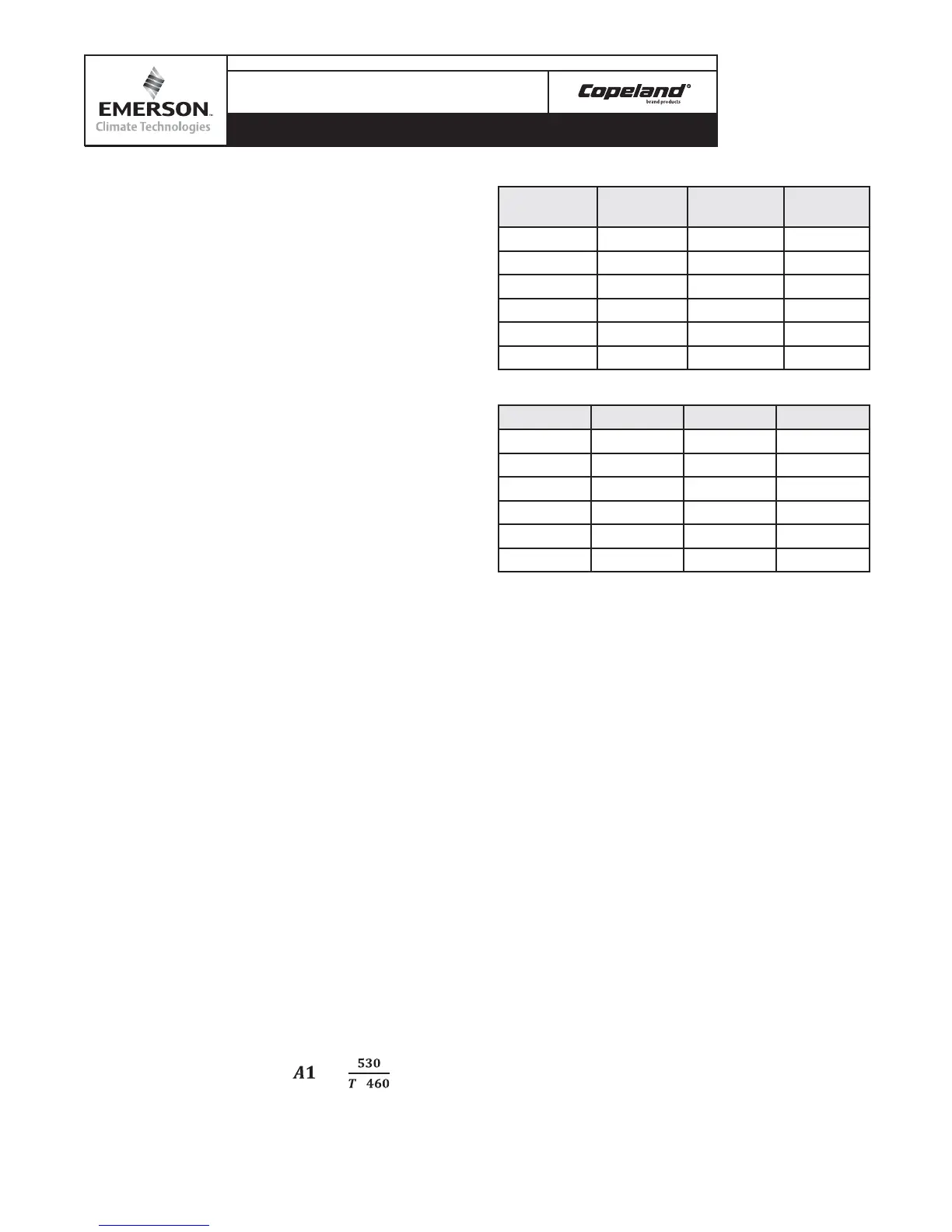
For temperature conversions
( )=
+
Temperature Conversion Factors
Temp
(degrees F)
Factor A1
Temp
(degrees F)
Factor A1
0 1.15 60 1.02
10 1.13 70 1.00
20 1.10 80 .98
30 1.08 90 .96
40 1.06 100 .95
50 1.04 110 .93
Altitude Conversion Factors (A2)
Alt.- Ft. Factor- A2 Alt.- Ft Factor- A2
0 1.00 3000 .895
500 .982 4000 .864
1000 .965 5000 .832
1500 .947 6000 .802
2000 .930 7000 .771
2500 .912 8000 .743
SCFM= CFM X A1 X A2
Note: all calculations and ratings are based on standard
air at 70°F dry bulb temp and 29.92 Hg atmospheric
pressure (sea level). These tables convert non standard
cfm to standard cfm.
Performance Data
See Tables 1 and 2 (page 10).
Electrical / Physical Data
See
Table 3
(page 11).
Generator Requirements
In situations or locations were an electrical power
generator could be applied in the event of a power
outage, the Copeland Scroll
®
outdoor condensing unit
will operate providing the generator will provide a supply
voltage range of 180-260 VAC along with a frequency
of 47-63 Hz. The electronics control along with the
power board will function properly providing the range
of operating limits is in compliance!
Physical Dimensions
See Figure 2 (page 7).
Installation / Piping Instructions
See Figure 2 for overall dimensions of the units. It is
recommended that a clearance of 8 inches from the
 Loading...