Site Considerations for Equipment Installation, Grounding, and Wiring Manual
D301452X012
October 2019
34 Grounding and Bonding of Solar PV Array
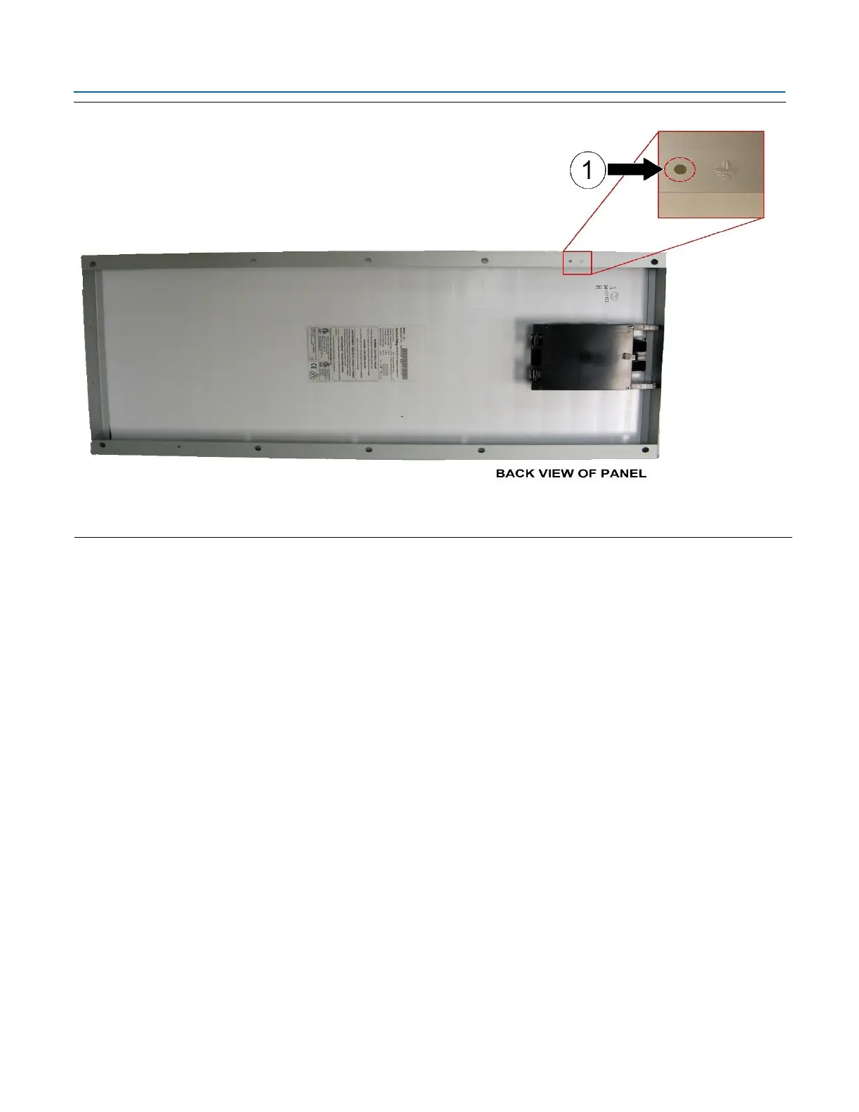
Figure 6-1. Model 30J 30W Solar Panel Protective Grounding
Note that for other solar panels without a specific earth grounding point (like the Model 30J) you
may employ any available mounting hole that is not already being used to mount the panel for this
purpose or you may drill a new hole in an appropriate location.
6.3 Non-Conductive Components
Be wary of fiberglass and other non-conductive materials that may have been employed in the solar
panel mounting assembly (such as for a mounting pole). These non-conductive components
cannot serve as part of the electrical path between the solar panel mounting frame and earth
ground. Bypass such components using a suitably sized electrical conductor to establish a complete
and uninterrupted ground circuit between the solar panel frame and earth ground.
6.4 Non-Conductive Coatings
It is both important and necessary to ensure that you remove any non-conductive coatings present
on the surface of the metal solar panel mounting frame from the contact area of the selected
grounding point to ensure a good (low resistance) electrical connection. Solar panel frame
components are typically aluminum or galvanized steel. Anodizing (a common surface treatment
used to add corrosion resistance to aluminum) is an electrolytic passivation process which grows a
surface layer of aluminum oxide over the aluminum. The resulting coating may be anywhere from a
few microns (type I) to over a hundred microns (type III) thick depending upon the type of
anodizing used. Anodizing provides a surface that is corrosion resistant, hard, and non-conductive
and, unlike paint, is not easily worn away. Consequently, to establish a low resistance ground
connection you must break through this surface to reach the underlying conductive aluminum.
 Loading...