4 U.L. Model No.: CF4800/CF4500
How To Put Your
Ceiling Fan Together
1. Position the fan motor and housing assembly in the
lower foam packing so that the top of the motor is
facing you.
2. Separate, untwist and unkink the four motor leads.
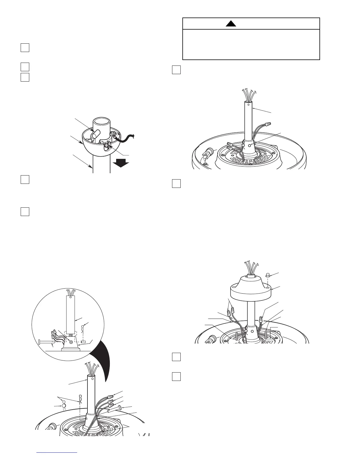
3. Obtain the hanger ball/downrod assembly and
remove the hanger ball by loosening the setscrew
in the hanger ball until the ball falls freely down the
downrod (Figure 1). Remove the pin from the
downrod , then remove the hanger ball. Retain the
pin and hanger ball for reinstallation in Step 6.
4. Route the white, blue, and black motor leads
through the downrod. Fold the yellow wire into the
slot in the motor coupling, slide the downrod down
the wires and seat the downrod in the motor
coupling (Figure 2).
5. Align the clevis pin holes in the downrod with the
holes in the motor coupling. Install the clevis pin
and secure with the hairpin clip (Figure 2). The
clevis pin must go through the holes in the motor
coupling and the holes in the downrod. Push the
straight leg of the hairpin clip through the hole near
the end of the clevis pin until the curved portion of
the hairpin clip snaps around the clevis pin. The
hairpin clip must be properly installed to prevent
the clevis pin from working loose. Pull on the
hanger ball to make sure the clevis pin is properly
installed.
PIN
HANGER
BALL
SETSCREW
DOWNROD
Figure 1
SETSCREW
CLEVIS PIN
MOTOR
COUPLING
DOWNROD
HAIRPIN
CLIP
MOTOR
COUPLING
HAIRPIN
CLIP
CLEVIS
PIN
DOWNROD
BROWN LEAD
RED LEAD
CLEVIS PIN
YELLOW LEAD
FROM UPLIGHT
YELLOW LEADS
Figure 2
6. Install the setscrew (supplied in loose parts bag) in
the motor coupling and tighten using the 5/32"
setscrew wrench (supplied) (Figure 3).
7. Screw two 1” threaded studs (provided) into the
motor (Figure 4). Leave approximately 7/8” of the
stud extending above the motor. Slide the motor
cover over the downrod and rotate the cover until
the threaded studs protrude; install two knurled
knobs (supplied) to secure the cover.
NOTE: Make sure the red and brown leads are
capped with wire connectors. Make sure the red,
brown, and yellow wires and wire connectors are
completely inside motor coupling cover and not
pinched between the motor coupling cover and
motor.
8. Position the ceiling cover over the downrod. Be
sure the cover is oriented correctly, with the large
opening at the top (Figure 5).
9. Reinstall the hanger ball on the downrod as
follows. Route the motor leads through the hanger
ball and slide the hanger ball over the downrod
(Figure 5). Install the pin through the holes at the
top of the downrod and slide the hanger ball up
the downrod, aligning the ball so the pin is
captured in the groove in the top of the hanger
ball. Pull the hanger ball up tight against the pin
and securely tighten the setscrew in the hanger
ball. A loose setscrew could create fan wobble.
DOWNROD
SETSCREW
Figure 3
It is critical that the clevis pin in the motor coupling
is properly installed and the setscrew securely
tightened. Failure to verify that the pin and setscrew
are properly installed could result in the fan falling.
WARNING
!
7/8"
RED LEAD
WIRE
CONNECTORS
KNURLED KNOB
1" THREADED
STUD
MOTOR
MOTOR
COUPLING
COVER
WIRE CONNECTOR
YELLOW LEADS
BROWN LEAD
Figure 4
 Loading...