EasyManua.ls Logo

Enerpac BVS4 - User Manual

Enerpac BVS4
8 pages
Print Icon
To Next Page IconTo Next Page
Loading...
®
A UNIT OF APPLIED POWER INC.
INSTALL ALL KIT COMPONENTS TO INSURE OPTIMUM PERFORMANCE OF THE REPAIRED PUMP.
L-2236
Rev. O
04/97
PC5240
Repair Parts Sheet
BVS4 / BVR4
Figure 1 - Valve Assembly
Parts List
Item No. Part Number Qty. Description
1 DA1269900SR 1 Solenoid Ass’y.
2 Std. Hardware 4 Cap Screw #10-32 x 2" Lg.
3 Std. Hardware 4 Lock Washer (for a #10 screw)
4 4 O-Ring
5 CL99950W 1 Valve Block Ass’y.
6 1 Gasket
7 DA973950SR 1 Valve to Adapter
Connector Ass’y.
8 2 Back-up Washer
9 2 O-Ring
10 Std. Hardware 6 Cap Screw
5
/
16
- 18 x 1
1
/
4
" Lg.
11 F132038 1 Manifold (BVS4)
11 F130038 1 Manifold (BVR4)
12 Std. Hardware 4 Cap Screw
1
/4 -
20 x 1
3
/
4
" Lg.
13 Std. Hardware 1 Plug
1
/
8
" N.P.T.F. (BVS4)
13 Std. Hardware 2 Plug
3
/
8
" N.P.T.F. (BVR4)
14 BSS5899D 1 Connector
15 1 Gasket
17 2 Back-up Washer
18 4 O-Ring
19 DA973950SR 1 Connector (incl. item 8,9)
BSS57330SR 1 Remote Pendant
Indicates items included in and available only as part of
Repair Kit VS4-24K1.
For date codes beginning with "D"
Question and Answer IconNeed help?

Do you have a question about the Enerpac BVS4 and is the answer not in the manual?

Enerpac BVS4 Specifications

General IconGeneral
BrandEnerpac
ModelBVS4
CategoryControl Unit
LanguageEnglish

Summary

Enerpac BVS4;BVR4 Repair Parts Sheet

Figure 1 Valve Assembly Parts List

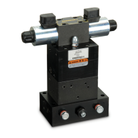
Provides a detailed parts list and diagram for the main valve assembly, including solenoids and connectors.

Figure 2 Valve Block Assembly

Illustrates and lists components of the valve block assembly, detailing balls, seats, springs, and seals.

Figure 3 Solenoid Assembly

Details the solenoid assembly, including rectifier, coils, and terminal box, with a wiring diagram.

Troubleshooting and Maintenance Procedures

Troubleshooting Valve Malfunctions

Guides users through diagnosing common issues like pressure loss, leaks, and directional control problems.

Valve Disassembly Steps

Provides a step-by-step guide for safely disassembling the valve, including component removal order.

Valve Reassembly and Adjustments

Valve Reassembly Guide

Details the process of reassembling the valve using new parts, including torque specifications.

Valve Adjustments and Testing

Explains how to adjust pilot relief and pilot settings, and test valve operation for proper performance.

Enerpac Contact and Warranty Information

Related product manuals