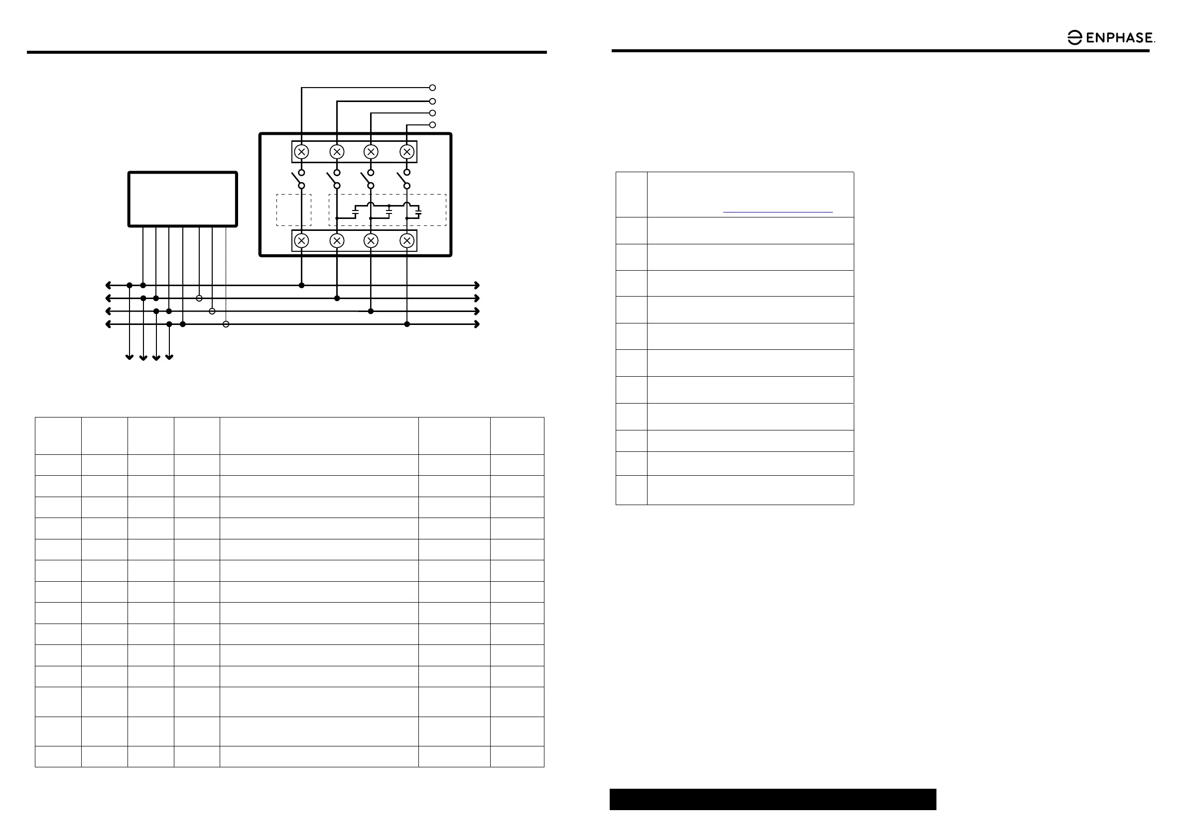
Q-RELAY-2-3P-ITA WIRING DIAGRAM
FROM
SOLAR
INVERTERS
N L1 L2 L3
N L1 L2 L3
L1
L2
L3
N
I1
I2
I3
ENVOY-S
N
L1
L2
L3
N
L1
L2
L3
TO AC
GRID
Q-RELAY-2-3P-ITA
PHASE
COUPLER
PRODUCTION
CTs
TO
STORAGE
(OPTIONAL)
TO
ADDITIONAL
Q-RELAYs
(IF REQUIRED)
DC I
SENSE
LED #1
(Voltage,
V1-N)
LED #2
(Voltage,
V2-N)
LED #3
(Voltage,
V3-N)
LED #4
(Hz, DCI(Di-
rect Current
Injection))
Description Condition Relay
OFF OFF OFF OFF Description/Status Unpowered or
non-functional
OPEN
GREEN
(solid)
X X X Phase voltage (V1-N) is within range. -- --
X GREEN
(solid)
X X Phase voltage (V2-N) is within range. -- --
X X GREEN
(solid)
X Phase voltage (V3-N) is within range. -- --
X X X GREEN
(solid)
Frequency and DCI (if applicable) are all within spec. -- --
GREEN
(solid
GREEN
(solid)
GREEN
(solid)
GREEN
(solid)
Voltage, frequency and DCI (if applicable) are all within spec. Normal CLOSED
RED (solid) X X X Phase voltage (V1-N) setpoints (HV1, HV2, LV1, LV2 or LV3)
has timed out or the reconnection value has not been met.
FAULT OPEN
X RED (solid) X X Phase voltage (V2-N) setpoints (HV1, HV2, LV1, LV2 or LV3)
has timed out or the reconnection value has not been met.
FAULT OPEN
X X RED (solid) X Phase voltage (V3-N) setpoints (HV1, HV2, LV1, LV2 or LV3)
has timed out or the reconnection value has not been met.
FAULT OPEN
X RED
(ashing)
X X Voltage detected on phase 2 (V2-N) but this phase is not
congured. Recongure phases.
ERROR Normal
operation
X X RED
(ashing)
X Voltage detected on phase 3 (V3-N) but this phase is not
congured. Recongure phases.
ERROR Normal
operation
X X X RED (solid) Grid frequency (V1) has timed out or reconnect frequency
hasn't been met yet or the DCI threshold is met (if used) and
the relay is opened.
FAULT OPEN
RED (solid) RED (solid) RED (solid) RED (solid) TEST button is being pushed. Test contactor and
autocong phase
assignments
Toggle state
RED/GREEN
(ashing)
RED/GREEN
(ashing)
RED/GREEN
(ashing)
RED
(ashing)
Corrupt FLASH FAULT OPEN
LED BEHAVIOR
Q-RELAY-2-3P-ITA WIRING DIAGRAM
SAFETY
IMPORTANT SAFETY INSTRUCTIONS.
SAVE THIS INFORMATION.
Follow all safety and assembly instructions when installing the
Q Relay.
Safety Instructions
+
DANGER: Risk of electric shock. Risk of re. Do not attempt to re-
pair the Q Relay; it contains no user-serviceable parts. Tampering
with or opening the Q Relay will void the warranty. Warranty void
if cover removed. If the Q Relay fails, contact Enphase Customer
Support for assistance (http://enphase.com/global/contact/).
+
DANGER: Risk of electric shock. Always open or disconnect circuit
from power-distribution system (or service) of building and PV
side before installing or servicing the Q Relay.
+
DANGER: Risk of electric shock. Do not use Enphase equipment in
a manner not specied by the manufacturer. Doing so may cause
death or injury to persons, or damage to equipment.
+
DANGER: Risk of electric shock. Risk of re. Only qualied person-
nel should troubleshoot, install, or replace the Q Relay.
+
DANGER: Risk of electric shock. The Q Relay is intended for in-
stallation in an electrical enclosure (i.e. switchgear) that prevents
Operator access to hazardous live parts.
*
WARNING: Before installing or using the Q Relay, read all instruc-
tions and cautionary markings in the technical description and on
the Q Relay.
*
WARNING: Risk of equipment damage. When installing the Q Re-
lay in an enclosure, choose an area for installation where ambient
temperature remains between -40º C and 50º C.
*
WARNING: The temperature of the terminals may exceed 60º C.
Use an appropriately temperature-rated cable to connect to the
terminals.
*
WARNING: The circuit breaker must be suitably located and easily
reached. It must also be marked as the disconnecting device for
the PV system.
✓
NOTE: Perform all electrical installations in accordance with all
national and local electrical codes.
✓
NOTE: Install a residual current circuit breaker if required by
national regulations.
✓
NOTE: To ensure optimal reliability and to meet warranty require-
ments, the Enphase Q Relay must be installed according to the
instructions in this guide.
Enphase Customer Support: enphase.com/global/contact
 Loading...