EVCO S.p.A. | EV3 CHIL | Instruction sheet ver. 1.0 | Code 1043CHILI104 | Page 1 of 2 | PT 21/15
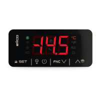
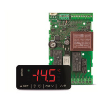
EV3 CHIL
Controller for single-circuit chillers
I
ENGLISH
IMPORTANT
Read this document carefully before installation and before
using the device and take all the prescribed precautions. Keep
this document with the device for future consultation.
Only use the device in the ways described in this document.
Do not use the device as safety device.
For more information see the installer manual.
The device must be disposed of according to local
regulations governing the collection of electrical and
electronic waste.
1 MEASUREMENTS AND INSTALLATION
1.1 Measurements
Measurements are expressed in mm (inches).
1.2 Installation
To be installed on a panel with snap-in brackets.
INSTALLATION PRECAUTIONS
- The thickness of the panel on which the device is to
be installed must be between 0.8 and 2.0mm (0.031
and 0.078 in).
- Ensure that the working conditions for the device
(operating temperatures, humidity, etc.) are within
the set limits. See the section TECHNICAL
SPECIFICATIONS.
- Do not install the device close to heat sources
(heating elements, hot air ducts, etc.), equipment
with a strong magnetic field (large diffusers, etc.), in
places subject to direct sunlight, rain, damp,
excessive dust, mechanical vibrations or shocks.
- In compliance with safety regulations, the device
must be installed properly to ensure adequate
protection from contact with electrical parts. All
protective parts must be fixed in such a way as to
need the aid of a tool to remove them.
2.1 I/O configuration
ANALOGUE INPUTS
IN1 Condensation temperature/pressure (NTC/4-20 mA)
IN2
System return temperature (NTC)
IN3
System delivery temperature (NTC)
IN4
Compressor discharge temperature (NTC)
DIGITAL INPUTS
IN5
System flow switch
IN10
On/Off
IN9
Fan thermal protection
IN8
Compressor 1 thermal protection
IN7
Maximum pressure switch
IN6
Minimum pressure switch
ANALOGUE OUTPUTS
AO1
Compressor 1 (0-10 V/phase cutting/PWM)
AO2
Fan (0-10V/phase cutting/PWM)
DIGITAL OUTPUTS
DO1
Alarm
DO2
Enable fan
DO3
Circulation pump
DO4
Enable compressor 1
TK1
Compressor 2 (if installed)
TK2
Fan (if installed)
2.2 Description of connectors
Connector 1
PART
DESCRIPTION
1
Electro-mechanical relay digital outputs DO1... DO4
(max. 6A): common
2
Electro-mechanical relay digital output DO4 (2A
SPST): normally open
3
Electro-mechanical relay digital output DO3 (2A
SPST): normally open
4
Electro-mechanical relay digital output DO2 (2A
SPST): normally open
5
Electro-mechanical relay digital output DO1 (2A
SPST): normally open
Connector 2
PART
DESCRIPTION
1 Dry contact digital input IN6
2 Analogue input IN1 (NTC/4-20 mA)
3 Dry contact digital input IN7
4 Analogue input IN2 (NTC)
5 Dry contact digital input IN8
6 Analogue input IN3 (NTC)
7 Dry contact digital input IN9
8 Analogue input IN4 (NTC)
9 Dry contact digital input IN10
10 Digital input IN5
11 Analogue output AO1 (0-10V/phase cutting/PWM)
12
Analogue input GND, digital input GND, analogue
output GND and GND for powered INTRABUS port
13 Analogue output AO2 (0-10V/phase cutting/PWM)
14 INTRABUS port powered up signal
15
Power supply to transducer analogue inputs 4-20
mA (12 VDC, max. 40 mA)
16
Analogue input GND, digital input GND, analogue
output GND and GND for powered INTRABUS port
17 EV3 CHIL power supply (12VAC not insulated)
18 EV3 CHIL power supply (12VAC not insulated)
Connector 3 (if installed)
PART
DESCRIPTION
1 RS-485 MODBUS slave port: +
2 RS-485 MODBUS slave port: --
3 RS-485 MODBUS slave port: shield
Connector 4 (if installed)
PART
DESCRIPTION
1 Triac TK1 output: GND
2 Triac TK1 output (200 mA): OUT
Connector 5 (if installed)
PART
DESCRIPTION
1 Triac TK2 output: GND
2 Triac TK2 output (2 A): OUT
2.3 Example of electrical connection
See next page.
PRECAUTIONS FOR ELECTRICAL CONNECTION
- Do not use electric or pneumatic screwdrivers on the
terminal blocks of the device.
- If the device has been moved from a cold to a warm
place, the humidity may cause condensation to form
inside. Wait about an hour before switching on the
power.
- Make sure that the supply voltage, electrical
frequency and power are within the set limits. See
the section TECHNICAL SPECIFICATIONS.
- Disconnect the device from the power supply before
doing any type of maintenance.
- The devices must be fed by power of the same
phase as that feeding any module with a phase-
cutting command signal.
- If using triac digital outputs, we recommend
connecting a noise filter; do not touch the heat
dissipator because it could be very hot
- Connect the device to an RS-485 network using a
screened twisted pair. We recommend using a
BELDEN 3106A cable.
- Connect the power cables as far away as possible
from those for the signal.
- For repairs and for further information on the device,
contact the EVCO sales network.
3 SIGNALS AND ALARMS
3.1 Signals
LED
DESCRIPTION
Function mode LED
Compressor 1 LED
Compressor 2 LED
Circulation pump LED
Fan LED
Temperature LED
Pressure LED
Alarm LED
Set-up LED
On/stand-by LED
3.2 Alarms
CODE
DESCRIPTION
EA01
Condensation temperature probe alarm/
condensation pressure probe alarm
EA02
System return temperature probe alarm
EA03
System delivery temperature probe alarm
EA04 Compressor discharge temperature probe alarm
AFLo Flow switch alarm
AHtr Maximum temperature alarm
AFr1 Antifreeze alarm
AHP1 Maximum pressure switch alarm
ALP1
Minimum pressure switch alarm
AtC1 Compressor 1 thermal protection alarm
AtF1
Fan thermal protection alarm