EVCO S.p.A. | EV3221 & EV3231 | Instruction sheet ver. 1.0 | Code 1043221E103 | Page 1 of 2 | PT 30/16
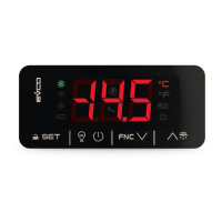
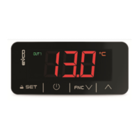
EV3221 & EV3231
Controllers for refrigerated cabinets, undercounters and islands,
with energy-saving strategies
E ENGLISH
- controllers for normal temperature units
- power supply 230 VAC
- cabinet probe (PTC/NTC)
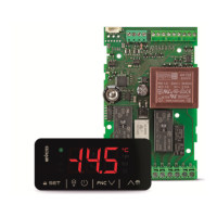
- compressor relay 16 A res. @ 250 VAC or 30 A res. @ 250 VAC (according to the
model)
- TTL MODBUS slave port for BMS
- cooling or heating operation.
1 MEASUREMENTS AND INSTALLATION
Measurements in mm (inches). To be fitted to a panel, snap-in brackets provided.
INSTALLATION PRECAUTIONS
- The thickness of the panel must be between 0.8 and 2.0 mm (1/32 and 1/16 in)
- Ensure that the working conditions are within the limits stated in the TECHNICAL
SPECIFICATIONS section.
- Do not install the device close to heat sources, equipment with a strong magnetic field,
in places subject to direct sunlight, rain, damp, excessive dust, mechanical vibrations
or shocks.
- In compliance with safety regulations, the device must be installed properly to ensure
adequate protection from contact with electrical parts. All protective parts must be
fixed in such a way as to need the aid of a tool to remove them.
2 ELECTRICAL CONNECTION
N.B.
- Use cables of an adequate section for the current running through them.
- To reduce any electromagnetic interference connect the power cables as far away
as possible from the signal cables.
PRECAUTIONS FOR ELECTRICAL CONNECTION
- If using an electrical or pneumatic screwdriver, adjust the tightening torque.
- If the device has been moved from a cold to a warm place, the humidity may have
caused condensation to form inside. Wait about an hour before switching on the
power.
- Make sure that the supply voltage, electrical frequency and power are within the set
limits. See the section TECHNICAL SPECIFICATIONS.
- Disconnect the power supply before doing any type of maintenance.
- Do not use the device as safety device.
- For repairs and for further information, contact the EVCO sales network.
3 FIRST-TIME
1. Install following the instructions given in the section MEASUREMENTS AND INSTALLA-
TION.
2. Power up the device as shown in the section ELECTRICAL CONNECTION and an internal
test will be run.
The test normally takes a few seconds, when it is finished the display will switch off.
3. Configure the device as shown in the section Setting configuration parameters.
Recommended configuration parameters for first-time use.
PAR. DEF. PARAMETER MIN... MAX.
SP 0.0 setpoint r1... r2
P0 1 probe type 0 = PTC 1 = NTC
P2 0 temperature unit of measurement 0 = °C 1 = °F
Then check that the remaining settings are appropriate; see the section CONFIGURA-
TION PARAMETERS.
4. Disconnect the device from the mains.
5. Make the electrical connection as shown in the section ELECTRICAL CONNECTION with-
out powering up the device.
6. For the connection in an RS-485 network connect the interface EVIF22TSX or
EVIF23TSX, to activate real time functions connect the module EVIF23TSX; see the
relevant instruction sheets.
7. Power up the device.
4 USER INTERFACE AND MAIN FUNCTIONS
4.1 Switching the device on/off
1.
If POF = 1, touch the ON/STAND-BY key for 2 s.
If the device is switched on, the display will show the P5 value ("cabinet temperature" default);
if the display shows an alarm code, see the section ALARMS.
LED ON OFF FLASHING
compressor on
compressor off
- compressor protection active
- setpoint setting active
defrost active
-
dripping active
HACCP
saved HACCP alarm
-
new HACCP alarm saved
energy saving active
-
-
request for compres-
sor service
-
- settings active
- access to additional functions
active
°C/°F
view temperature
-
overcooling or overheating active
device off
device on
device on/off active
If 30 s have elapsed without the keys being pressed, the display will show the “Loc” label and
the keypad will lock automatically.
4.2 Unlock keypad
Touch a key for 1 s: the display will show the label “UnL”.
4.3 Set the setpoint
Check that the keypad is not locked.
1.
Touch the SET key.
2.
Touch the UP or DOWN key within 15 s to set the value within
the limits r1 and r2 (default “-50... 50”)
3.
Touch the SET key (or do not operate for 15 s).
4.4 Activate manual defrost
Check that the keypad is not locked and that overcooling is not active.
1.
Touch the UP key for 2 s.
If P4 = 1, defrost is activated provided that the evaporator temperature is lower than the d2
threshold.
4.5 Silence buzzer (if present and A13 = 1)
Touch a key.
5 ADDITIONAL FUNCTIONS
5.1 Activate/deactivate overcooling, overheating and manual energy saving
Check that the keypad is not locked.
1.
Touch the DOWN key.
FUNCTION CONDITION CONSEQUENCE
overcooling
r5 = 0, r8 = 1 and defrost
not active
the setpoint becomes “setpoint -
r6”, for the r7 duration
overheating
r5 and r8 = 1
the setpoint becomes “setpoint +
r6”, for the r7 duration
energy saving
r5 = 0 and r8 = 2
the setpoint becomes “setpoint +
r4”, at maximum for HE2 duration
5.2 View/delete HACCP alarm information
Check that the keypad is not locked.
1.
Touch the DOWN key for 4 s.
2.
Touch the UP or DOWN key within 15 s to select a label.
LAB. DESCRIPTION
LS view HACCP alarm information
rLS delete HACCP alarm information
3.
Touch the SET key.
4.
Touch the UP or DOWN key to select an alarm code (when label
“LS” is selected) or to set “149” (when label “rLS” is selected).
COD. DESCRIPTION
AL low temperature alarm
AH high temperature alarm
id door switch alarm
PF power failure alarm (only if module EVIF23TSX is connected)
5.
Touch the SET key.
6.
Touch the ON/STAND-BY key (or do not operate for 60 s) to exit
the procedure.
Example of alarm information (e.g. a high temperature alarm).
8.0
critical value (cabinet/ calculated product temperature)
was 8.0 °C/°F
Sta (only if module EVIF23TSX is connected)
y15 alarm signalled in 2015
n03 alarm signalled in March
d26 alarm signalled on 26 March 2015
h16 alarm signalled at 16:00
n30 alarm signalled at 16:30
dur
h01 alarm lasted 1h
n15 alarm lasted 1h 15 min
5.3 View/delete compressor functioning hours and view compressor start-up
number
Check that the keypad is not locked.
1.
Touch the DOWN key for 4 s.
2.
Touch the UP or DOWN key within 15 s to select a label.
LAB. DESCRIPTION
CH view compressor functioning hours (hundreds)
rCH delete compressor functioning hours
nS1 compressor start-up number (thousands)
3.
Touch the SET key.
4.
Touch the UP or DOWN key to set “149” (when label “rCH” is se-
lected).
5.
Touch the SET key.
6.
Touch the ON/STAND-BY key (or do not operate for 60 s) to exit
the procedure.
5.4 View the temperature detected by the probes
Check that the keypad is not locked.
1.
Touch the DOWN key for 4 s.
2.
Touch the UP or DOWN key within 15 s to select a label.
LAB. DESCRIPTION
Pb1 cabinet temperature
Pb2 auxiliary temperature (if P4 = 1 or 2)
3.
Touch the SET key.
4.
Touch the ON/STAND-BY key (or do not operate for 60 s) to exit
the procedure.
5.5 View the project number and the firmware revision
Check that the keypad is not locked.
1.
Touch the DOWN key for 4 s.
2.
Touch the UP or DOWN key within 15 s to select a label.
LAB. DESCRIPTION
PrJ view the project number
rEU view the firmware revison
3.
Touch the SET key.
4.
Touch the ON/STAND-BY key (or do not operate for 60 s) to exit
the procedure.
6 SETTINGS
6.1 Setting configuration parameters
1.
Touch the SET key for 4 s: the display will show the label “PA”.
2.
Touch the SET key.
3.
Touch the UP or DOWN key within 15 s to set the PAS value (de-
fault “-19”).
4.
Touch the SET key (or do not operate for 15 s): the display will
show the label “SP”.
5.
Touch the UP or DOWN key to select a parameter.
6.
Touch the SET key.
7.
Touch the UP or DOWN key within 15s to set the value.
8.
Touch the SET key (or do not operate for 15 s).
9.
Touch the SET key for 4 s (or do not operate for 60 s) to exit the
procedure.
6.2 Set the date, time and day of the week (only if module EVIF23TSX is con-
nected)
N.B.
Do not disconnect the device from the mains within two minutes since the setting of
the time and day of the week.
Check that the keypad is not locked.
1.
Touch the DOWN key for 4 s.
2.
Touch the UP or DOWN key within 15 s to select the label “rtc”.
3.
Touch the SET key: the display will show the label “yy” followed
by the last two figures of the year.
4.
Touch the UP or DOWN key within 15 s to set the year.
5. Repeat actions 3. and 4. to set the next labels.
LAB. DESCRIPTION OF THE NUMBERS FOLLOWING THE LABEL
n month (01… 12)
d day (01… 31)
h time (00… 23)
n minute (00… 59)
6.
Touch the SET key: the display will show the label for the day of
the week.
7.
Touch the UP or DOWN key within 15s to set the day of the
week.
LAB. DESCRIPTION
Mon Monday
tuE Tuesday
UEd Wednesday
thu Thursday
Fri Friday
Sat Saturday
Sun Sunday
8.
Touch the SET key: the device will exit the procedure.
9.
Touch the ON/STAND-BY key to exit the procedure beforehand.
6.3 Restore the factory settings (default) and store customized settings as default
N.B.
- Check that the factory settings are appropriate; see the section CONFIGURATION
PARAMETERS.
- the storing of customized settings overwrites the default.
1.
Touch the SET key for 4 s: the display will show the label “PA”.
2.
Touch the SET key.
3.
Touch the UP or DOWN key within 15 s to set the value.
VAL. DESCRIPTION
149 value to restore the factory settings (default)
161 value to store customized settings as default
4.
Touch the SET key (or do not operate for 15 s): the display will
show the label “dEF” (when value “149” is set) or the label
“MAP” (when value “161” is set).
5.
Touch the SET key.
6.
Touch the UP or DOWN key within 15 s to set “4”.
7.
Touch the SET key (or do not operate for 15 s): the display will
show for 4 s “- - -“ flashing, then the device will exit the proce-
dure.
8. Interrupt the power supply to the device.
9.
Touch the SET key 2 s before action 6. to exit the procedure be-
forehand.
7 CONFIGURATION PARAMETERS
N. PAR. DEF. SETPOINT MIN... MAX.
1 SP 0.0 setpoint r1... r2; see r0
N. PAR. DEF. ANALOGUE INPUTS MIN... MAX.
2 CA1 0.0 cabinet probe offset -25... 25 °C/°F
3 CA2 0.0 auxiliary probe offset -25... 25 °C/°F
4 P0 1 probe type 0 = PTC 1 = NTC
5 P1 1 enable °C decimal point 0 = NO 1 = YES
6
P2
0
temperature unit of measure-
ment
0 = °C 1 = °F
7
P4
0
configurable input function
0 = digital input (door
switch/multipurpose
input)
1... 2 = analogue input (aux-
iliary probe)
0 = door switch/multipur-
pose input
1 = evaporator probe
2 = condenser probe