EVCO S.p.A. | EVJ 200 | Instruction sheet ver. 2.0 | Code 104J200I203 | Page 1 of 4 | PT 18/17
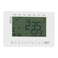
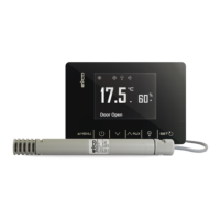
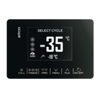
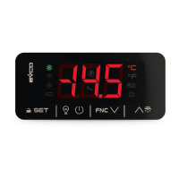
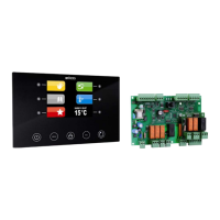
EVJ 200
Extra-large controllers for refrigerated cabinets and display units,
with energy-saving strategies
EN
ENGLISH
- Controllers for low temperature units.
- Power supply 230 VAC.
- Incorporated clock (according to the model).
- Cabinet probe and evaporator probe (PTC/NTC).
- Door switch input.
- Compressor relay 16 A res. @ 250 VAC or 30 A res. @ 250 VAC (according to the
model).
- Alarm buzzer.
- TTL MODBUS slave port for EVconnect APP or BMS.
- Port for SD card data-logger module EVBD05 (according to the model).
- Models in plastic container or open-frame (according to the model).
1 MEASUREMENTS AND INSTALLATION | Measurements in mm (inches)
1.1 Models in plastic container
According to the model, front installation on a plastic or metal panel (with elastic holding flaps)
or installed from behind a glass or methacrylate panel (with biadhesive) customizing the keys
on the front of the unit.
N.B.
For models for front installation: the thickness of a metal panel must be between
0.8 and 1.5 mm (1/32 and 1/16 in), while that for a plastic panel must be between
0.8 and 3.4 mm (1/32 and 1/8 in).
For models installed from behind: the thickness of the panel must be between
2.0 and 4.0 mm (1/16 and 1/8 in); the panel and the material used to make screen
printing must not contain conductive substances.
1.2 Open-frame models
To be installed from behind, with threaded studs and membrane keypad.
INSTALLATION PRECAUTIONS
- Ensure that the working conditions are within the limits stated in the TECHNICAL
SPECIFICATIONS section.
- Do not install the device close to heat sources, equipment with a strong magnetic field,
in places subject to direct sunlight, rain, damp, excessive dust, mechanical vibrations
or shocks.
- In compliance with safety regulations, the device must be installed properly to ensure
adequate protection from contact with electrical parts. All protective parts must be
fixed in such a way as to need the aid of a tool to remove them.
2 ELECTRICAL CONNECTION
N.B.
- Use cables of an adequate section for the current running through them.
- To reduce any electromagnetic interference connect the power cables as far away
as possible from the signal cables.
PRECAUTIONS FOR ELECTRICAL CONNECTION
- If using an electrical or pneumatic screwdriver, adjust the tightening torque.
- If the device has been moved from a cold to a warm place, the humidity may have
caused condensation to form inside. Wait about an hour before switching on the
power.
- Make sure that the supply voltage, electrical frequency and power are within the set
limits. See the section TECHNICAL SPECIFICATIONS.
- Disconnect the power supply before doing any type of maintenance.
- Do not use the device as safety device.
- For repairs and for further information, contact the EVCO sales network.
3 FIRST-TIME USE
1. Install following the instructions given in the section MEASUREMENTS AND
INSTALLATION.
2. Power up the device and an internal test will be run.
The test normally takes a few seconds, when it is finished the display will switch off.
3. Configure the device as shown in the section Setting configuration parameters.
Recommended configuration parameters for first-time use.
PAR.
DEF.
PARAMETER
MIN... MAX.
SP 0.0 setpoint r1... r2
P0 1 probe type 0 = PTC 1 = NTC
P2 0 temperature unit of measurement 0 = °C 1 = °F
d1
0
defrost type
0 = electric 1 = hot gas
2 = compressor stopped
Then check that the remaining settings are appropriate; see the section
CONFIGURATION PARAMETERS.
4. Disconnect the device from the mains.
5. Make the electrical connection as shown in the section ELECTRICAL CONNECTION
without powering up the device.
6. For the connection in an RS-485 network connect the interface EVIF22TSX or
EVIF23TSX, to activate real time functions in EVJ203, EVJ204, EVJ205, EVJ224 and
EVJ225 connect the module EVIF23TSX, for recording HACCP data in CSV format on SD
card connect the module EVBD05, to use the device with the Android APP EVconnect
connect the interface EVIF25TBX (or use EVJ214N7VXXRXV, EVJ234 or EVJ235); see
the relevant instruction sheets. If EVIF22TSX or EVIF23TSX is used, set
parameter bLE to 0.
7. Power up the device.
4 USER INTERFACE AND MAIN FUNCTIONS
4.1 Switching the device on and off
1.
If POF = 1 (default), touch the ON/STAND-BY key for 2s.
If the device is switched on, the display will show the P5 value ("cabinet temperature" default);
if the display shows an alarm code, see the section ALARMS.
LED
ON
OFF
FLASHING
compressor on
compressor off
- compressor protection active
- setpoint being set
evaporator fan on
evaporator fan off
evaporator fan stop active
cabinet light on
cabinet light off
cabinet light on by digital input
AUX 1
auxiliary function 1 on
auxiliary function 1 off
- auxiliary function 1 on by digital
input
- auxiliary function 1 delay active
AUX 2
auxiliary function 2 on
auxiliary function 2 off
- auxiliary function 2 on by digital
input
- auxiliary function 2 delay active
defrost or pre-drip
active
-
- defrost delay active
- dripping active
- energy saving active
- low consumption
active
-
-
view time
-
set date, time and day of the
current week
view temperature
-
overcooling or overheating active
HACCP
saved HACCP alarm
-
new HACCP alarm saved
alarm active
-
-
If Loc = 1 (default) and 30s have elapsed without the keys being pressed, the display will show
the “Loc” label and the keypad will lock automatically.
4.2 Unlock keypad
Touch a key for 1s: the display will show the label “UnL”.
4.3 Set the setpoint (if r3 = 0, default)
Check that the keypad isn’t locked.
1.
Touch the SET key.
2.
Touch the UP or DOWN key within 15s to set the value within the
limits r1 and r2 (default “-40... 50”)
3.
Touch the SET key (or do not operate for 15s).
4.4 Activate manual defrost (if r5 = 0, default)
Check that the keypad is not locked and that overcooling is not active.
1.
Touch the DEFROST key for 2s.
If P3 = 1 (default), defrost is activated provided that the evaporator temperature is lower than
the d2 threshold.
4.5 Cabinet light on/off (if u1c... u5c = 5)
1.
Touch the CABINET LIGHT key.
4.6 Button-operated load on/off (if u1c... u5c = 10 or 11)
1.
Touch the CABINET LIGHT key (for 2s if u1c... u5c = 5).
If u1c... u5c = 6, the demisting switch on for the u6 duration.
4.7 Silence buzzer (if u9 = 1, default)
Touch a key.
If u1c... u5c = 11 and u4 = 1, the alarm output is deactivated.
5 ADDITIONAL FUNCTIONS
5.1 Activate/deactivate overcooling and overheating
Check that the keypad is not locked.
1.
Touch the UP key for 2s.
FUNCTION CONDITION CONSEQUENCE
overcooling
r5 = 0 and defrost not
active
the setpoint becomes “setpoint -
r6”, for the r7 duration
overheating
r5 = 1
the setpoint becomes “setpoint +
r6”, for the r7 duration
5.2 Activate/deactivate energy saving in manual mode (if r5 = 0)
Check that the keypad is not locked.
1.
Touch the DEFROST key.
The setpoint becomes “setpoint + r4”, at maximum for HE2 duration.
5.3 Activate the high or low humidity functions (if F0 = 5)
Check that the keypad isn’t locked.
1.
Touch the DOWN key for 1s.
2.
Touch the UP or DOWN key within 15s to select the label “rH”.
3.
Touch the SET key for 2s until the display shows the right label
for the function (only touch the key to see the function
activated).
LAB.
DESCRIPTION
rhL
low humidity function (evaporator fan with F17 and F18 if the compressor is
off, on if the compressor is on)
rhH
high humidity function (evaporator fan on)
4.
Touch the ON/STAND-BY key (or do not operate for 60s) to exit
the procedure.
5.4 View/delete HACCP alarm information (not available in EVJ203, EVJ204,
EVJ205, EVJ224 and EVJ225)
Check that the keypad isn’t locked.
1.
Touch the DOWN key for 1s.