rol Panel
CONTROL SYSTEM
K6
K7
R6
R7
C7
+
C6
+
D11
D12
D10
D6
D4
D9
D5
D3
D21
D22
D20
D19
D24
D23
D25
D26
C
W
Y
R
ZONE 2
T'STAT
C
W
Y
R
R1
0
B
G
ZONE 1
T'STAT
CAUTION
0
R
C
+
-
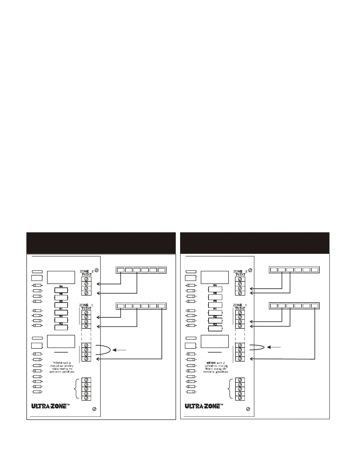
ADDITIONAL
ZONE PANEL
#1: WIRING DIAGRAM
HEATING ONLY INSTALLATION
rol Panel
K6
K7
R6
R7
C7
+
C6
+
D11
D12
D10
D6
D4
D9
D5
D3
D21
D22
D20
D19
D24
D23
D25
D26
C
W
Y
R
ZONE 2
T'STAT
C
W
Y
R
R1
0
B
G
ZONE 1
T'STAT
CAUTION
0
R
C
+
-
ADDITIONAL
ZONE PANEL
#2: WIRING DIAGRAM
COOLING ONLY INSTALLATION
AP PL ICA TIO N NO TES
OPERATION
To operate the system in the heat mode,
the "B" terminal has to be made to the "R1"
terminal on the zone 1 terminal block. This
allows any zone thermostat to call for heat.
When a zone calls for heat, the control
panel closes the circuit from "R" to "W"
activating the furnace. The zone damper
calling for heat remains open and zones
satisfied will close. The fan and limit control
in the furnace will operate the fan.
1. HEAT MODE:
2. COOL MODE:
To operate the system in the cool mode,
the "O" terminal has to be made to the "R1"
terminal on the zone 1 terminal block. This
allows for any thermostat to call for cooling.
On call for cooling, terminals "R", "G" and
"Y" are made to bring on the fan and
compressor. The dampers for zones calling
will remain open; the dampers satisfied will
close.
3. OFF POSITION:
When the subbase on zone 1 is in the
"OFF" position the entire system is disabled.
4. CONTINUOUS FAN:
When placing the fan switch on the
subbase from "AUTO" to "ON" position, the
panel closes the circuit between "R" and "G"
terminals to energize the fan relay.
5. OPEN-CLOSE SWITCHES:
If left in the open position when all zones
satisfy, the damper will drive to open
position. If left in closed position, when all
zones satisfy , the damper will remain
closed unless it is the last zone to satisfy;
then it will remain open.
NOTE: The last zone to satisfy will always
be open regardless of position of switch.
WIRING
1. HVAC SYSTEM:
Wiring the HVAC system to the EWC-ST-2E
or EWC-ST-3E is typical of wiring a subbase
to a heating/cooling system. (4 wires
required.)
The following terminals are on the system
terminal block:
R-
Y-
W-
G-
Wire to the RH heating transformer
and/or the RC cooling transformer.
Wire to the Compressor Relay.
Wire to Heat Control (gas valve, oil
burner relay) on system terminal block.
Wire to Fan Relay.
2. TRANSFORMER 24V 40VA:
A separate 24V 40VA transformer is required
to be wired to terminals 1 and 2 of the
terminal block labeled "T-Former". (2 wires
required.) This transformer powers the panel
board, thermostats and damper motors. It
does not power the furnace or the air
conditioner. The board is now protected by
a Thermal Polyfuse at the transformer input.
When the polyfuse trips it will get quite hot. To
reset the breaker, remove the 24 VAC for
approximately 30 seconds. Check the damper
motors and field wiring for shorts. If adding two
panels together, be sure of wiring in (+ and - )
circuit.
3. ZONE DAMPER MOTORS:
Use 3 conductor wire from each set of MAN
or RDN zone damper terminals or 2
conductor wire on "SR" dampers to the
panel. See diagrams #4 and 5 when wiring
more than one damper per zone.
ZONE 1: Thermostats that have subbases
with "B" and "O" terminals are required to
enable system changeover. These include
mechanical and battery operated
thermostats (6 wires required - terminals W,
Y, G, R, B and O), and electro-mechanical
and programmable digital thermostats (24
VAC, 7 wires required - terminals C, W, Y,
G, R, B and O).
If model MCS-DXB remote selector switch is
used, it will be wired to the zone 1 terminal
block in place of the changeover subbase
(7 wires required total: 4 on the MCS-DXB -
B, G, O and R1; 3 on the thermostat - W,
Y and R). See diagram #3.
OTHER ZONES: 3 wires are required for
mechanical and battery operated
thermostats - terminals W, Y and R. 4 wires
are required for electro-mechanical and 24
VAC digital thermostats - terminals C, W, Y
and R. No subbases required.
See page 6 for specific types of
thermostats required.
4. THERMOSTATS:
5. HEAT ONLY OR COOL ONLY
Zone 1 no longer requires a subbase or
remote switch. All zones need only a two
or three wire thermostat to operate in either
heat or cool.
APPLICATIONS:
2
CONTROL SYSTEM
EWC Controls Inc. • 385 Highway 33 • Englishtown, NJ 07726 • 800-446-3110
•
FAX 732-446-5362
R
GYW
O
B
ZONE 2 THERMOSTAT
R
GYW
O
B
ZONE 1 THERMOSTAT
FIELD
INSTALLED
JUMPER
R
GYW
O
B
ZONE 2 THERMOSTAT
R
GYW
O
B
ZONE 1 THERMOSTAT
FIELD
INSTALLED
JUMPER
 Loading...