Panel
K6
K7
C
W
Y
R
ZONE 2
T'STAT
C
W
Y
R
R1
0
B
G
ZONE 1
T'STAT
CAUTION
0
R
C
+
-
PLEASE read all
instructions carefully
before starting the
installation procedures.
ADDITIONAL
ZONE PANEL
CONTROL SYSTEM
GREEN
BROWN
RED
ORANGE
RED
HEAT
OFF
COOL
FAN
ON
AUTO
Front of Plate
Back of Plate
#4: TYPICAL TANDEM
DAMPER WIRING
3
#3: EWC-ST-2E WITH MCS-DXB
REMOTE SELECTOR SWITCH
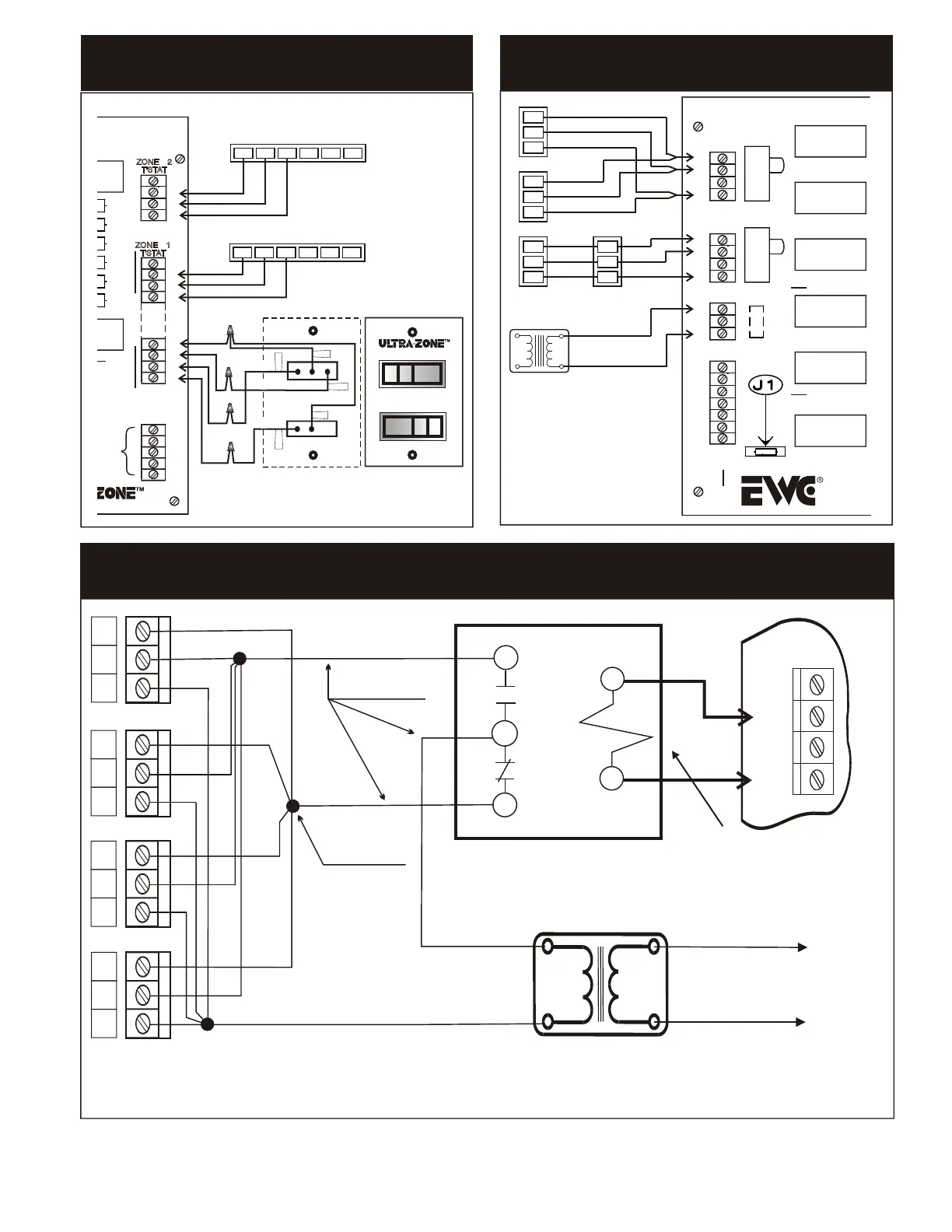
#5: CONTROL OF UP TO FOUR DAMPERS PER ZONE
USING EXTERNAL RELAY
K9
K8
X
R
G
W
Y
B
O
1
2
K4
SW1
24V
T'FORMER
K2
K1
K5
OPEN
CLOSE
OPEN
CLOSE
SW2
M1
M2
M4
M6
ZONE2
M1
M2
M4
M6
ZONE1
MOTOR
MOTOR
Model
CONTROLS
Englishtown
MA-ND4 TYPE MOTORS ON
ND OR URD TYPE DAMPERS
EWC Controls Inc. • 385 Highway 33 • Englishtown, NJ 07726 • 800-446-3110 • FAX 732-446-5362
CB1
RED
RED
BROWN
ORANGE
GREEN
1
6
4
1
6
4
1
6
4
1
6
4
24VAC TRANSFORMER
40 - 60VA RATING
MAX. NUMBER OF 4 DAMPERS
PER ZONE.
Multiple Damper Wiring on a Single Zone, using a Separate Transformer
and an Isolating Relay. Maximum of 4 dampers per 40 va transformer.
M1
M2
M4
M6
ZONE
MOTOR
4
6
1
4
6
1
4
6
1
2
1
3
COIL
24 vac
NC
NO
C
R1 Isolation Relay
SPDT action with 24 vac coil
Relay is shown de-energized.
All dampers are closed.
To Line Voltage
Provide over current
protection
4
6
1
Separate 24 vac
Transformer
TYPICAL FEEDER CONDUCTOR
TYPICAL JUNCTION POINT
L1
L2
H
C
One relay coil=One motor.
Don’t overload your power
transformer, by connecting
too many relays.
R
GYW
O
B
ZONE 2 THERMOSTAT
R
GYW
O
B
ZONE 1 THERMOSTAT
 Loading...