EasyManua.ls Logo

Extech Instruments 380260 User Manual

Extech Instruments 380260
8 pages
To Next Page IconTo Next Page
To Previous Page IconTo Previous Page
Page #3 background image
380260-en-EU_V2.5 8/14
3
Operation
Connecting Test Leads
For all measurements, connect the red test lead to the V input terminal and the black test lead to
the COM input terminal.
Test Lead Check
1. Set the rotary switch to the 200range.
2. Touch the test lead tips together.
3. Resistance should read less than 0.5 and the audio tone should sound.
4. With the leads not touching, the display should read infinity indicated by “1”.
5. Readings displayed other than the readings described above are indicative of a test lead
problem. The test leads must be replaced before using the meter. Failure to do so could result
in damage to equipment and electrical shock.
Insulation Resistance Measurements (Megohmmeter Tests)
Warning: Do not perform Insulation Resistance measurements if AC Voltage is present on the device
under test.
1. Connect the red test lead to the V input terminal; black lead to the COM terminal.
2. Set the function switch to the desired Mtest voltage position.
3. Connect the tips of the test leads to the equipment under test. If there is a voltage present, a
constant beep will sound and the voltage will be displayed.
4. The display will show “1“until the TEST button is pushed. Press and hold the TEST button. The
upper right display shows the test voltage applied and the flashing high voltage symbol
will
be displayed. The main display shows the resistance.
5. Keep the test leads connected to the equipment under test and release the TEST button. The
circuit will discharge through the meter. Keep the test leads connected until the circuit is
completely discharged and the upper right display shows 0 volts.
Lock Function
For hands-free operation, use the LOCK feature.
1. With the test leads connected to the equipment under test, simultaneously press the TEST and
LOCK keys.
2. The LOCK icon”
” will appear on the display. A beeper will sound every 2 seconds to
indicate that the meter is in Lock mode.
3. Press the LOCK key to disable the Lock function and end the test.
Warning
Ensure that the circuit under test does not include components that can be damaged by 1000VDC; such
devices include power factor correction capacitors, low voltage mineral insulated cables, electronic light
dimmers, and ballasts/starters for fluorescent lamps.
www.GlobalTestSupply.com
Find Quality Products Online at: sales@GlobalTestSupply.com
Question and Answer IconNeed help?

Do you have a question about the Extech Instruments 380260 and is the answer not in the manual?

Extech Instruments 380260 Specifications

General IconGeneral
Model380260
CategoryTest Equipment
Frequency Response31.5Hz to 8kHz
Power Supply9V battery
Resolution0.1°F/°C
Weighting NetworksA
Time WeightingFast

Summary

Introduction and Safety

Introduction

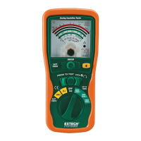
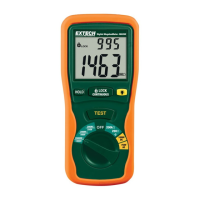
Congratulations on purchasing the Extech Insulation Tester/Megohmmeter Model 380260.

Safety Precautions

Essential safety guidelines for using the meter, including de-energizing circuits and avoiding contact with live conductors.

International Safety Symbols

Explanation of symbols used on the meter, such as caution and dangerous voltage indicators.

Meter Description

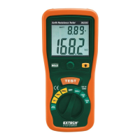
Identifies the main components of the meter, including the LCD display, buttons, and rotary switch.

Meter Operation and Features

Connecting Test Leads

Instructions for connecting the red and black test leads to the correct input terminals.

Test Lead Check

Procedure to verify the integrity and functionality of the test leads before use.

Insulation Resistance Measurement

Detailed steps for performing insulation resistance tests (Megohmmeter function).

Lock Function

Enables hands-free operation by locking the test function and providing audible feedback.

Notes on IR Testing

Important considerations and interpretations for insulation resistance (Megohmmeter) tests.

AC/DC Voltage Measurement

Procedure for measuring AC and DC voltages using the meter.

Resistance Measurement

Instructions for measuring resistance, including a warning about AC voltage presence.

Low Resistance (Continuity) Measurement

Procedure for checking continuity and low resistance values with audible indication.

Auto Power Off

Details the automatic power-off feature to conserve battery life.

Hold Function

Explains how to freeze the current reading on the display.

Backlight

Instructions for activating the display backlight.

Applications and Specifications

Measuring Power Tools and Small Appliances

Guidance on how to test devices that use a line cord, including double-insulated tools.

Testing AC Motors

Procedure for testing AC motors, including wiring connections and component checks.

Testing DC Motors

Steps for testing DC motors, focusing on brush rigging, field coils, and armature.

Testing Cables

Instructions for testing cable insulation resistance to ground and between conductors.

MEGOHMMETER RANGES

Detailed specifications for insulation resistance measurement ranges, accuracy, and terminal voltage.

AC VOLTAGE

Specifications for AC voltage measurement, including range, resolution, accuracy, and overload protection.

DC VOLTAGE

Specifications for DC voltage measurement, including range, resolution, accuracy, and overload protection.

RESISTANCE

Specifications for resistance measurement, including range, resolution, accuracy, and maximum open circuit voltage.

General specifications

Comprehensive specifications covering display, sampling rate, fuse, dimensions, weight, and approvals.

Maintenance

Battery Replacement

Step-by-step instructions for replacing the meter's batteries when the low battery symbol appears.

Cleaning

Guidelines for cleaning the instrument case using a dry cloth, avoiding solvents or abrasives.

Related product manuals