480400‐en‐EU_V3.39/14
4
Operation
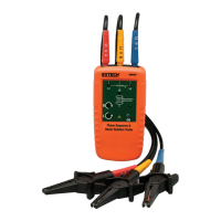
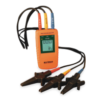
Determine Phase Rotation Direction
1. Connect the supplied color-coded test leads to the meter’s test lead input jacks at the top of the
meter.
2. Connect the test probes to the three mains phases for the system under test.
3. L1, L2, and L3 indicators will illuminate one at a time on the meter’s LCD display as each phase
is connected.
4. The clockwise and counter-clockwise arrows with the left/right ‘L’ or ‘R’ icons display the phase
rotation direction of the device under test.
5. The sequence grid simply shows the three line sequences for Clockwise ‘R’ and the three line
sequences for Counter-Clockwise ‘L’.
Note: The rotational arrow indicators illuminate even if one of the test probes is connected to a
neutral or ground conductor instead of one of the mains phases.
Specifications
Nominal Voltage 40 to 600 VAC
Frequency Range (fn) 15 to 400HZ
Current pickup 1 mA
Nominal Test current (in per phase) 1 mA
Maximum Operating Voltage (Ume) 600 V
Operating Temperature 0 to 40
o
C (32 to 104
o
F)
Type of protection IP 40
Dimensions (H x W x D): 130 x 69 x 32mm (5.1 x 2.7 x 1.3”)
Weight 130g (4.6 oz.)
Approvals CE (EU directives)
Safety For indoor use and in accordance with the requirements for double
insulation to IEC1010-1 (1995): EN61010-1 (1995) Overvoltage Category III
600V, Pollution Degree 2.
Copyright©2014FLIRSystems,Inc.
Allrightsreservedincludingtherightofreproductioninwholeorinpartinanyform
ISO‐9001Certified
www.extech.com
 Loading...