Operation
20
www.ferrisindustries.com
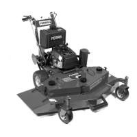
Figure 3. Checking Tire Pressure
Check Tire Pressures
Tire pressure should be checked periodically, and
maintained at the levels shown in the chart. Note that these
pressures may differ slightly from the “Max Inflation”
stamped on the side-wall of the tires. The pressures shown
provide proper traction, improve cut quality, and extend tire
life.
Tire
Pressure
psi bar
Deck Caster Tires 25 1,03
Drive Tires 10 0,69
Tractor Caster Tires
25 1,03
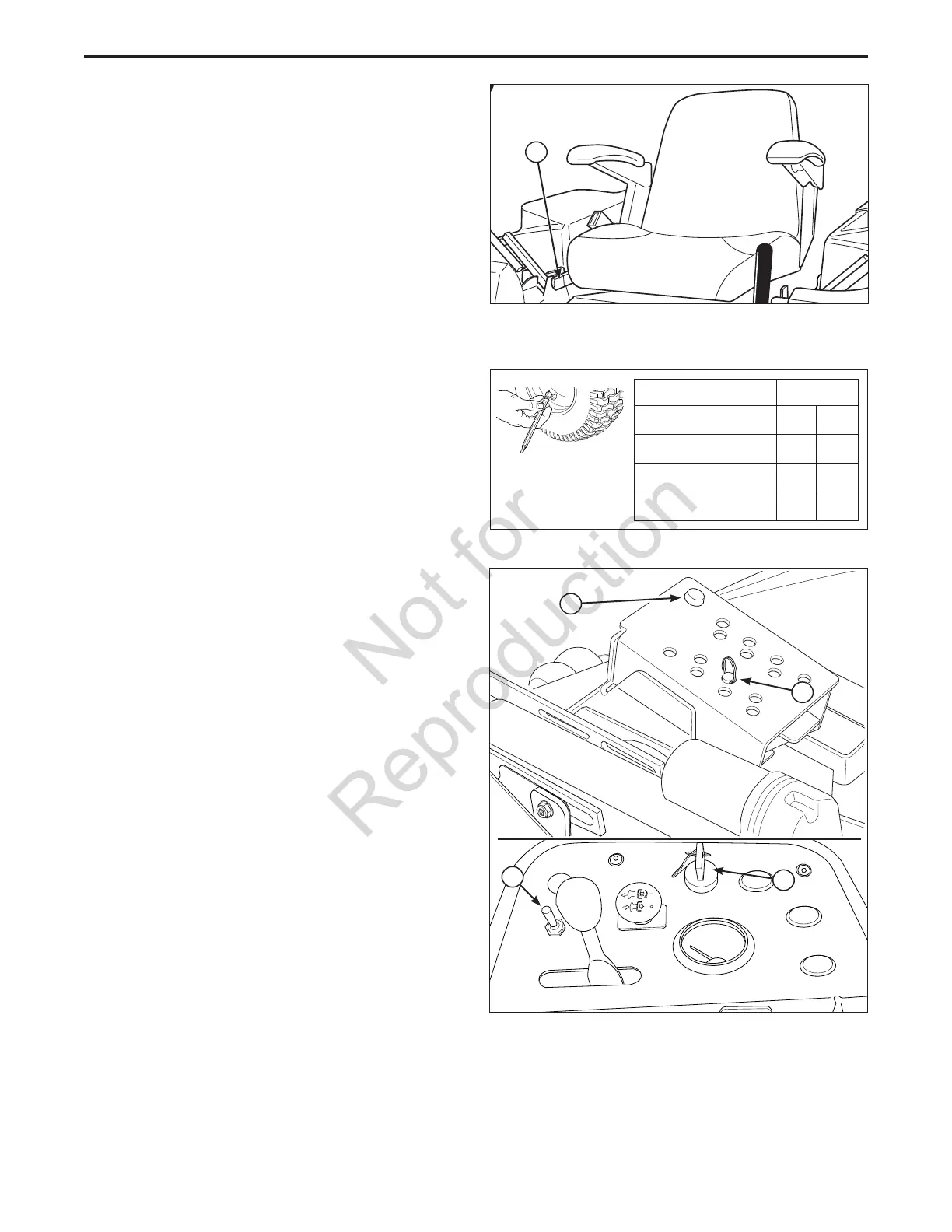
Mowing Height Adjustment
The cutting height adjustment pin (A, Figure 4) controls
the mower cutting height. The cutting height is adjustable
between 1-1/2” (3,37 cm) and 5” (12,7 cm) in 1/4” (0,64
cm) increments.
1. Turn the ignition key (C) to the RUN position.
2. Press the mower deck lift actuator switch (B) foward
(away from the operator) to remove the pressure from
the deck height adjustment pin.
3. Place the deck height adjustment pin in the desired
location.
4. Press the mower deck lift actuator switch backwards
(towards the operator) until contact is made with the
deck height adjustment pin. Continue to retract the
actuator until the operating position indicator lamp (D)
stops flashing and shuts off.
NOTE: The actuator MUST be positioned correctly before
attempting to move the ground speed control levers out of
their NEUTRAL positions. If the actuator is not positioned
as described in the above step the mower’s safety
interlock system will cause the engine to shut off.
Figure 4. Mowing Height Adjustment
A. Cutting Height Adjustment Pin
B. Actuator Deck Height Toggle Switch
C. Ignition Switch Key
D. Operating Position Indicator Lamp
A
C
B
D
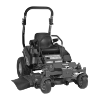
Seat Adjustment
S/N: 2014648788 & Above:
The seat can be adjusted forward and back. Move the seat
adjustment lever (A, Figure 2b) to the left, position the
seat as desired, and release the lever to lock the seat into
position.
A
Figure 2b. Seat Adjustment
A. Seat Adjustment Lever

 Loading...