44 www.ferrismowers.com
Transmission Drive Belt Replacement
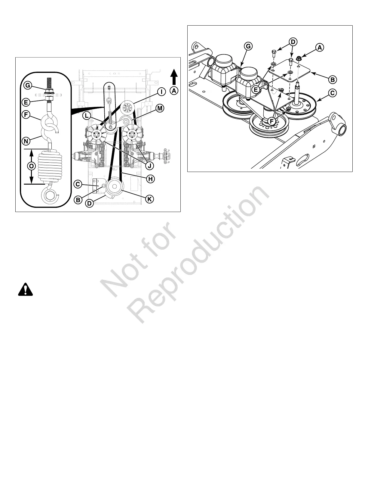
Figure 61 depicts the transmission drive belt setup as seen
from the top side of the unit and the arrow (A, Figure 61)
indicates the front of the unit.
61
1. Park the unit on a smooth, level surface such as a
concrete floor. Disengage the PTO, engage the parking
brake, turn off the ignition, and remove the key.
2. Remove the mower deck drive belt. See Mower Drive Belt
Replacement for removal instructions.
3. Remove the hardware (B) that secures the clutch anchor
pad (C) to the PTO clutch (D) and disconnect the wire
harness from the PTO clutch.
WARNING
STORED ENERGY DEVICE: Improper release of the belt
tension spring can result in personal injury. Use extreme
caution when removing the spring.
4. Loosen the jam nut (E) on the spring anchor eye bolt (F).
5. Loosen the adjustment nut (G) on the spring anchor
eye bolt to release the majority of the belt tension. Use
caution to remove the nut to completely release the
tension.
6. Loosen the 3/8" nylock flange nut (A, Figure 62) that
secures the pulley support plate (B) to the front stationary
pulley stack-up (C).
62
7. Remove the two (2) 5/16" bolts (D), 5/16" flat washers
(E), and 5/16" nylock flange nuts (F) that secure the
pulley support plate to the hydraulic tank mount plate (G).
Rotate the pulley support plate away from the hydraulic
tank mount so that the belt can be removed from the
machine.
8. Remove the old belt and replace with a new one (H,
Figure 61). Make sure that the V-side of the belt runs in
the grooves of the front stationary idler pulley (I), both
transmission pulleys (J) and the crankshaft pulley (K).
Make sure that the flat side of the belt contacts the faces
of the adjustable idler pulley (L) and the stationary idler
pulley (M).
9. Rotate the pulley support plate (B, Figure 62) back into
position and secure to the hydraulic tank mount plate (G)
using the two (2) 5/16" bolts (D), 5/16" flat washers (E),
and 5/16" nylock flange nuts (F).
10. Re-tighten the 3/8" nylock flange nut (A) that secures
the pulley support plate (B) to the front stationary pulley
stack-up (C).
11. Reinstall the spring anchor eyebolt (F, Figure 61) into the
spring anchor tab and loosely fasten the adjustment nut
(G).
12. Tighten the adjustment nut until the spring (N) achieves a
coil-to-coil measurement (O) of 5-3/4" (14,6 cm).
13. Tighten the jam nut (E).
14. Reinstall the clutch anchor pad (C) to the PTO clutch (D)
and secure using the hardware (B) previously removed.
Reconnect wire harness to the PTO clutch.
15. Reinstall the mower deck drive belt. See Mower Drive
Belt Replacement for instructions.
Suspension Adjustment
The shock assemblies (A, Figure 63) can be adjusted to allow
the operator to customize the ride according to operator’s
weight and/or operating conditions.
 Loading...