page 3
EXAMPLE: A gas fired appliance firing at 100,000 BTU/hr. where the CAS unit needs to be placed 30
equivalent feet from the intake hood.
From Diagram A or B, the point at 100,000 BTU/hr. on the Gas Firing Rate scale and 30 equivalent feet
falls in the 4" Duct, Hood, and Orifice Ring region. The point is approximately
2
⁄3 of the horizontal distance
between the left and right boundary of the region. The left boundary is the edge of the graph, the right
boundary is the diagonal line that says 4" Duct, Hood & Orifice Ring. Therefore, place the Orifice Ring into
the inlet of the CAS so that it sits on the ledge above the fan. It does not matter which way the Orifice Ring is
turned as long as it is pushed down against the ledge completely. Use 4" diameter pipe to connect the vent
hood and the CAS unit. Install a VRV and the included 4"x 6" increaser on top of the CAS unit and adjust the
balance weight to
2
⁄3 of the distance of its full adjustment range from its minimum setting. The minimum setting
is with the balance weight turned all of the way counterclockwise.
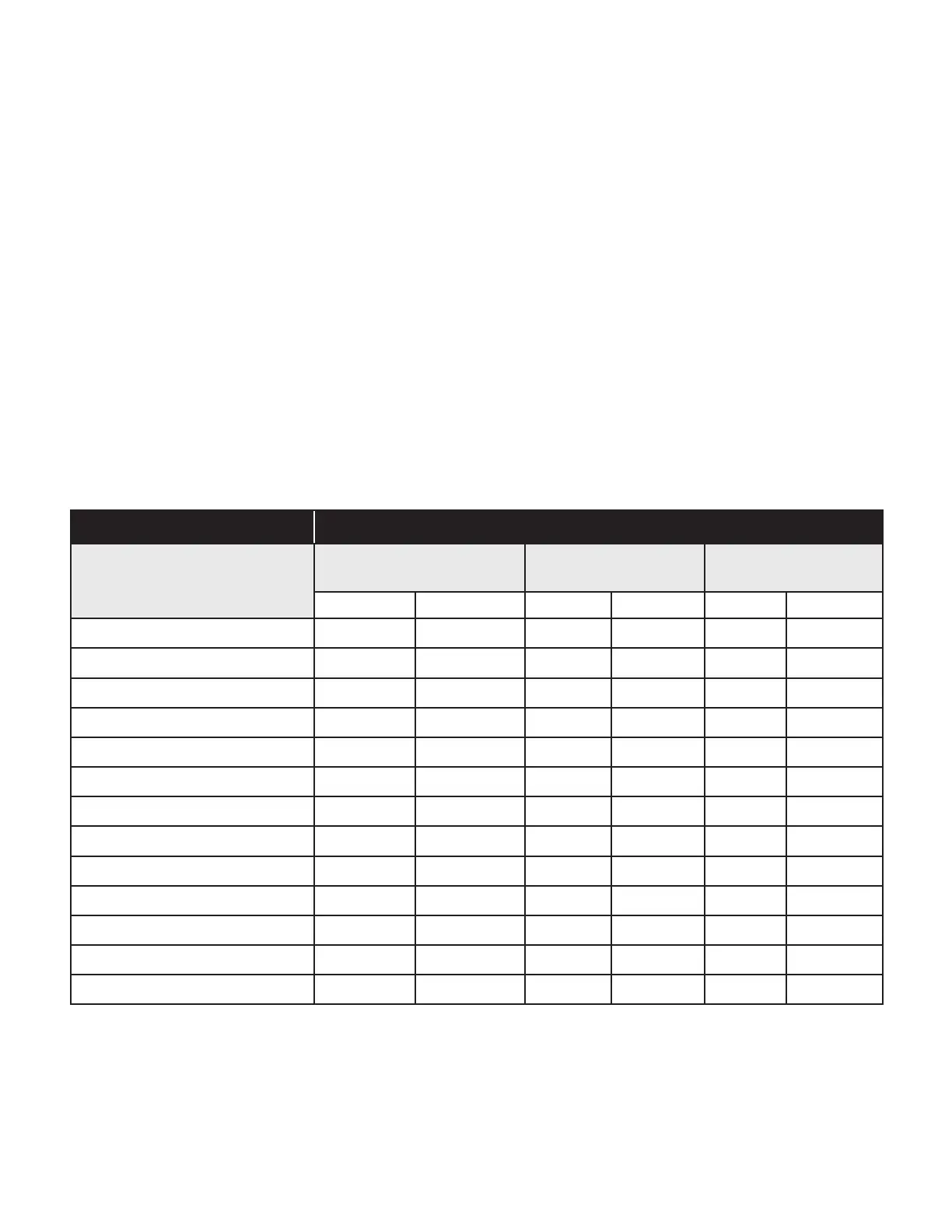
TOTAL INPUT OF APPLIANCE MAXIMUM EQUIVALENT FEET OF INSTALLATION
CAS-4, 4mV Gas
(BTU/hr.)
4" Duct And Hood w/
Restrictor
4" Duct and 4"
Intake Air Hood
6" Duct and 6"
Intake Air Hood
HI LOW HI LOW HI LOW
50,000 300 300 300 300 300 300
75,000 300 300 300 300 300 300
100,000 300 300 300 300 300 300
125,000 300 220 300 220 300 300
150,000 174 108 232 118 300 300
175,000 99 48 152 63 300 300
200,000 52 14 102 32 300 300
225,000 20 NA 68 13 300 239
250,000 NA NA 45 NA 300 150
300,000 NA NA 16 NA 300 53
350,000 NA NA NA NA 193 8
400,000 NA NA NA NA 109 NA
450,000 NA NA NA NA 56 NA
Draw a horizontal line on Diagram A or B that passes through the point located in step 5. The position of 8.
the point along this line relative to the left and right borders of the region it falls into indicates the relative
position that the balance weight of the VRV should be adjusted to. If the point falls near the leftward
border of a region, then the VRV balance weight should be adjusted to its minimum position. This
corresponds to turning the balance weight screw as far counterclockwise as possible.
Table 1
 Loading...