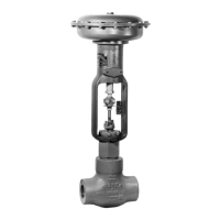
Designs D & DA
3
appropriate nameplates. Use pressure-
relieving devices as required by govern-
ment or accepted industry codes and
good engineering practices.
CAUTION
When ordered, the valve configuration
and construction materials were se-
lected to meet particular pressure, tem-
perature, pressure drop, and controlled
fluid conditions. Some body/trim materi-
al combinations are limited in their pres-
sure drop and temperature ranges. Do
not apply any other conditions to the
valve without first contacting your
Fisher Controls sales office or sales rep-
resentative.
1. Before installing the valve, inspect it to be certain
that the valve body cavity is free of foreign material.
Clean out all pipelines to remove scale, welding slag,
and other foreign materials.
2. Install the valve so that flow through the valve is in
the direction shown by the arrow cast on the valve
body. The control valve assembly may be installed in
any position unless limited by seismic considerations.
However, the normal method is with the actuator verti-
cal above the valve. With some valves, the actuator
may need support when it is not vertical. For more in-
formation, consult your Fisher Controls sales office or
sales representative.
3. Use accepted piping and welding practices when
installing the valve in the line. For flanged valve bo-
dies, use suitable gaskets between the body flanges
and pipeline flanges.
Note
Depending on valve body materials
used, post-weld heat treating might be
needed. If so, damage to internal elasto-
meric and plastic parts, as well as inter-
nal metal parts is possible. Shrink-fit
pieces and threaded connections may
also loosen. In general, if post-weld heat
treating is needed, remove all trim parts.
Contact your Fisher Controls sales of-
fice or sales representative for addition-
al information.
For screwed end connections, apply pipe compound to
pipeline threads.
4. To allow continuous operation during inspection or
maintenance, install a three-valve bypass around the
control valve assembly.
5. If you received the actuator and valve body
shipped separately, refer to the appropriate actuator
instruction manual for the actuator mounting proce-
dure.
WARNING
Personal injury could result from pack-
ing leakage. Valve packing was tight-
ened before shipment; however the
packing might require some readjust-
ment to meet specific service condi-
tions.
WARNING
Avoid personal injury from sudden re-
lease of process pressure. Before per-
forming any maintenance operations:
D Disconnect any operating lines pro-
viding air pressure, electric power, or a
control signal to the actuator. Be sure
the actuator cannot suddenly open or
close the valve.
D Use bypass valves or completely
shut off the process to isolate the valve
from process pressure. Relieve process
pressure on both sides of the valve.
Drain the process media from both
sides of the valve.
D Vent the pneumatic actuator load-
ing pressure and relieve any actuator
spring precompression.
D Use lock-out procedures to be sure
that the above measures stay in effect
while you work on the equipment.
Valve body parts are subject to normal wear and must
be inspected and replaced as necessary. Inspection
and maintenance frequency depends on the severity
of service conditions. This section includes instructions
for packing lubrication, packing maintenance, trim
maintenance, and lapping seating surfaces. All main-
tenance operations can be performed with the valve in
the line.

 Loading...