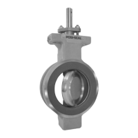
Design V260
2
Table 1. Specifications
Valve Body Size and End Connection Styles
(1)
8-, 10-, 12-, 16- and 20-inch flanged valves with
ANSI Class 150, 300 and 600 raised-face or ring-
type joint flanges compatible with ASME B16.5.
See table 2 for face-to-face dimensions
Maximum Inlet Pressures and Temperatures
(1)
Consistent with Class 300 or 600 pressure-tempera-
ture ratings per ASME B16.34
Maximum Allowable Shutoff Pressure Drop
(1)
For Single-Seal and Dual-Seal Construction:
(Except where further limited by the pressure-tem-
perature rating of valve body material)
For LF2 valve body material:
Class 300: 51 bar (740 psi) at 38_C (100_F)
Class 600: 103 bar (1480 psi) at 38_C (100_F)
Seal Material and Temperature Capability
(1)
J Delrin (Standard) –46 to 82_C (–50 to 180_F)
J PTFE/PEEK
(2)
(Optional) –46 to 232_C (–50 to
450_F)
J S31600 (316 SST)/Alloy 6 (Optional) Consult
factory
Flow Characteristic
Modified equal percentage
Flow and Shutoff Direction
Unidirectional flow for Design V260 is forward flow.
Seal is upstream.
J Single Seal Constructions: Should be used for
unidirectional flow and unidirectional shutoff only.
J Dual Seal Constructions: V260A and V260C
may be used for unidirectional or bidirectional flow.
V260B should be used for unidirectional flow only
for most effective anti-cavitation protection. Bidirec-
tional shutoff requires the dual seal construction.
Shutoff Classification
Single-Seal Composition Constructions: 0.001%
of maximum valve capacity (less than 10% of ANSI/
FCI 70-2 Class IV)
Dual-Seal Composition Constructions: 0.001% of
maximum valve capacity (less than 10% of ANSI/
FCI 70-2 Class IV)
Single-Seal Metal Constructions: Class IV per
ASME B16.34 FCI 70-2
Dual-Seal Metal Constructions: Class IV per
ASME B16.34 FCI 70-2
Maximum Ball Rotation
90 degrees
Actuator Mounting
Right-hand or left-hand mounted as viewed from the
valve inlet for forward flow
Approximate Weight
See table 2
1. The pressure-temperature limits in this instruction manual and any applicable standard or code limitation for valve should not be exceeded.
Table 2. Face-to-Face Dimensions and Approximate Weights
VALVE SIZE,
FACE-TO-FACE APPROXIMATE
INCHES
(CLASS 600
(1)
)
DIMENSIONS
WEIGHT
mm kg
8 661 424
10 788 653
12 840 882
16 990.6 2472
20 1144 4313
Inches Pounds
8 26.04 975
10 31.04 1550
12 33.07 2025
16 39.0 5450
20 47.0 9500
1. For Class 300 valves, face-to-face dimensions are the same as Class 600 valves.
Installation
WARNING
D Personal injury or equipment dam-
age can result from the sudden release
of process pressure if service conditions
can exceed valve or mating pipe flange
pressure ratings. To avoid such injury
or damage, provide a relief valve for
over-pressure protection as required by
government or accepted industry codes
and good engineering practices.

 Loading...