Design V260
5
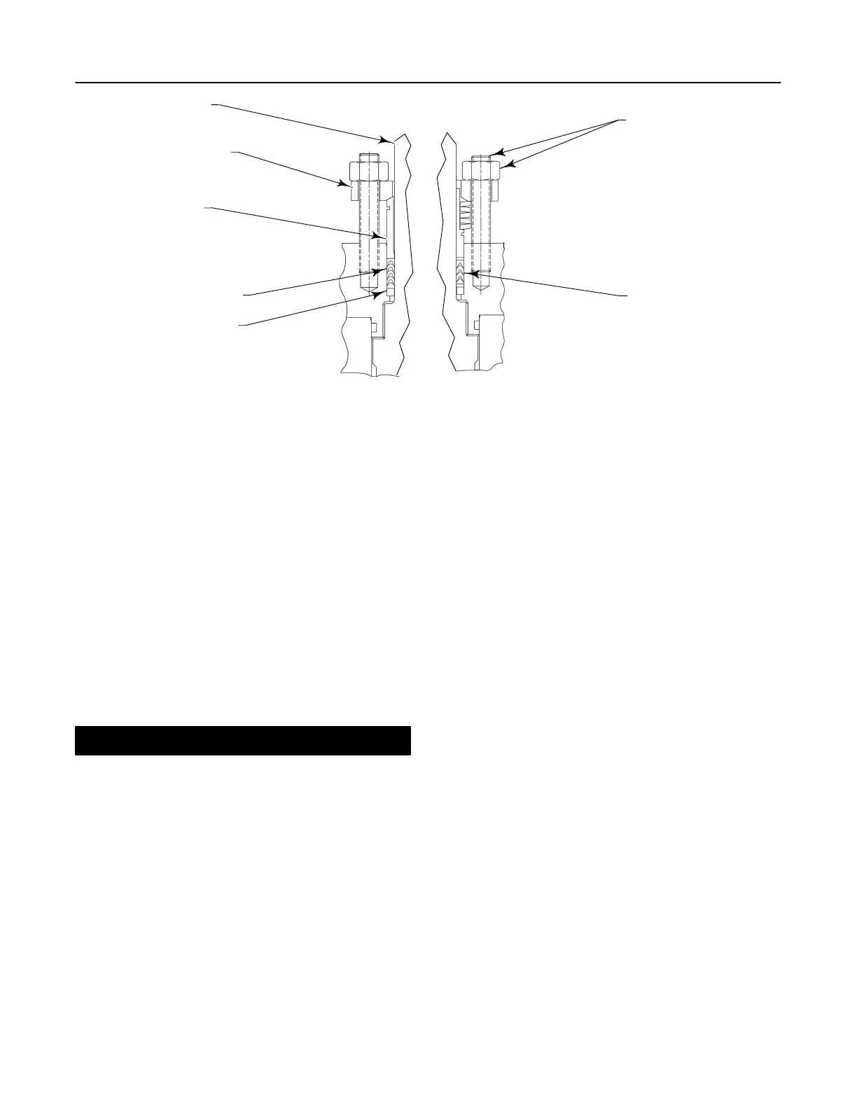
Figure 3. Packing Arrangement Details
PACKING FLANGE
(KEY 102)
DRIVE SHAFT
(KEY 20)
PACKING
FOLLOWER
(KEY 114)
TYPICAL PTFE
V-RING PACKING
SET (KEY 105)
PACKING BOX
RING (KEY 107)
PACKING STUD
AND NUT
(KEYS 100 & 101)
STANDARD
PACKING ARRANGEMENT
ENVIROĆSEAL
PACKING ARRANGEMENT
TYPICAL
ENVIRO-SEAL
PTFE V-RING
PACKING SET
94BA02200-D
B2472-1 /IL
3. Remove the actuator cover. Note and mark the
orientation of the actuator with respect to the valve
body and the lever orientation with respect to the valve
drive shaft, to assist with reassembly.
4. Loosen the lever locking device cap screw. Loos-
ening the lever turnbuckle adjustment is not necessary
during disassembly. When remounting the actuator,
the turnbuckle will be used for actuator adjustments.
5. Removing the actuator from the valve:
a. Remove the actuator mounting screws, bolts, or
nuts.
CAUTION
When removing the actuator from the
valve, do not use a hammer or similar
tool to drive the lever or actuator off the
valve shaft. Driving the lever or actuator
off the valve shaft could damage the
ball, seal(s), and valve.
If necessary, use a wheel puller to re-
move the lever or actuator from the
valve shaft. Tap the wheel puller screw
lightly to loosen the lever or actuator. Do
not hit the screw with excessive force.
Using excessive force could damage the
ball, seal(s), and valve.
b. Slide the lever along the valve shaft while re-
moving the actuator from the valve.
6. If necessary, remove the bonding strap assembly,
shown in figure 2, from the valve before attempting to
remove the packing box parts.
7. Remove the packing follower nuts, packing flange,
and packing follower (keys 101, 102, and 114,
figure 3).
8. Remove the packing parts:
a. If the packing housing (key 16) is mounted
on the valve: Use a formed wire hook with a sharp
end to pierce the packing rings, and pull the rings
out of the packing box. Do not scratch the drive
shaft or packing box wall. Scratching these sur-
faces could cause leakage. Clean, inspect, and
obtain replacement parts as necessary for reas-
sembly.
b. If the packing housing is removed from the
valve: Remove the drive shaft (key 20) from the
packing housing. With the drive shaft removed,
remove all internal parts. Clean, inspect, and ob-
tain replacement parts as necessary for reas-
sembly.
The packing sets (key 105) listed in the parts list do
not include any metal parts. Either clean and reuse
metal packing parts or obtain replacements by order-
ing them individually.