Specifications and Related Documents
November 1999
5-1
5-5 5
Table 5-1. Specifications
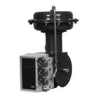
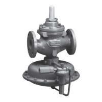
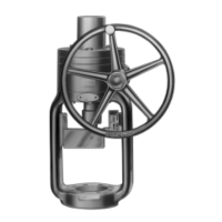
Available Configurations
Type DVC5010: Sliding stem applications—Fisher
Controls actuator Types 657 and 667
Type DVC5020: Rotary applications—Fisher
Controls actuator Types 1051 and 1052
Type DVC5030: Rotary applications—Fisher
Controls actuator Types 1066SR, 1051, 1052, and
other quarter-turn actuators
Type DVC5040: Sliding-stem application—Fisher
Controls System 9000 actuator
DVC5000 Series digital valve controllers can be
mounted on those actuators listed as well as on
other Fisher and other manufacturers rotary and
sliding-stem actuators
Input Signal
Point-to-Point:
Analog Input Signal: 4 to 20 mA dc, nominal
Minimum Voltage Available at instrument terminals
must be 11.5 Vdc for analog control, 12 Vdc for
HART communication (see instrument instruction
manual for details)
Minimum Control Current: 4.0 mA
Minimum Current w/o Microprocessor Restart: 3.5
mA
Maximum Voltage: 30 volts dc
Overcurrent Protection: Input circuitry limits current
to prevent internal damage (Hardware revisions 4
and 5 only. Instruments with earlier hardware
revisions may be damaged if connected directly to a
voltage source while in point-to-point mode.)
Reverse Polarity Protection: No damage occurs
from reversal of loop current
Multi-drop:
Instrument Power: 12 to 30 volts dc at
approximately 8 mA
Reverse Polarity Protection: No damage occurs
from reversal of loop current
Output Signal
(1)
Pneumatic signal as required by the actuator, up to
95% of supply pressure
Minimum Span: 0.4 bar (6 psig)
Maximum Span: 6.2 bar (90 psig)
Action: Direct only
Supply Pressure
(1)
Minimum and Recommended: 0.3 bar (5 psi)
higher than maximum actuator requirements
Maximum: 6.9 bar (100 psig)
Steady-State Air Consumption
(1,2)
At 1.4 bar (20 psig) supply pressure: Less than 0.3
normal m
3
/hr (10 scfh)
At 2.4 bar (35 psig) supply pressure: Less than 0.4
normal m
3
/hr (15 scfh)
At 4.1 bar (60 psig) supply pressure: Less than 0.6
normal m
3
/hr (22 scfh)
At 6.9 bar (100 psig) supply pressure: Less than 0.9
normal m
3
/hr (34 scfh)
Maximum Output Capacity
(2)
At 1.4 bar (20 psig) supply pressure: 7.6 m
3
/hr (285
scfh)
At 4.1 bar (60 psig) supply pressure: 17.6 normal
m
3
/hr (658 scfh)
Independent Linearity
(1)
±0.5% of output span
Electromagnetic Interference (EMI)
Output signal changes less than ±0.1% when tested
per IEC 801-1 and 801-3, 27 to 1000 MHz with field
strength of 30 V/m (volts per meter)
These instruments have the CE mark in accordance
with the Electromagnetic Compatibility (EMC)
Directive. They meet the requirements of
EN50081-1 (emissions for light industry) and
EN50082-2 (immunity for industrial environment).
Electrical Classification
Hazardous Area: Explosion-proof, intrinsically
safe, Division 2, and flameproof constructions
available to CSA, FM, CENELEC, and SAA
standards. Refer to Hazardous Area Classification
Bulletins 9.2:001 series and 9.2:002.
Electrical Housing: Meets NEMA 4X, IEC 529
IP65
Connections
Supply Pressure: 1/4-inch NPT female and
integral pad for mounting 67CFR regulator
Output Pressure: 1/4-inch NPT female
Tubing: 3/8-inch metal
Vent (pipe-away): 1/4-inch NPT female
Electrical: 1/2-inch NPT female, M20 female, or G
1/2 parallel (bottom entrance)
–continued–
5

 Loading...


