7
Installation and Connections
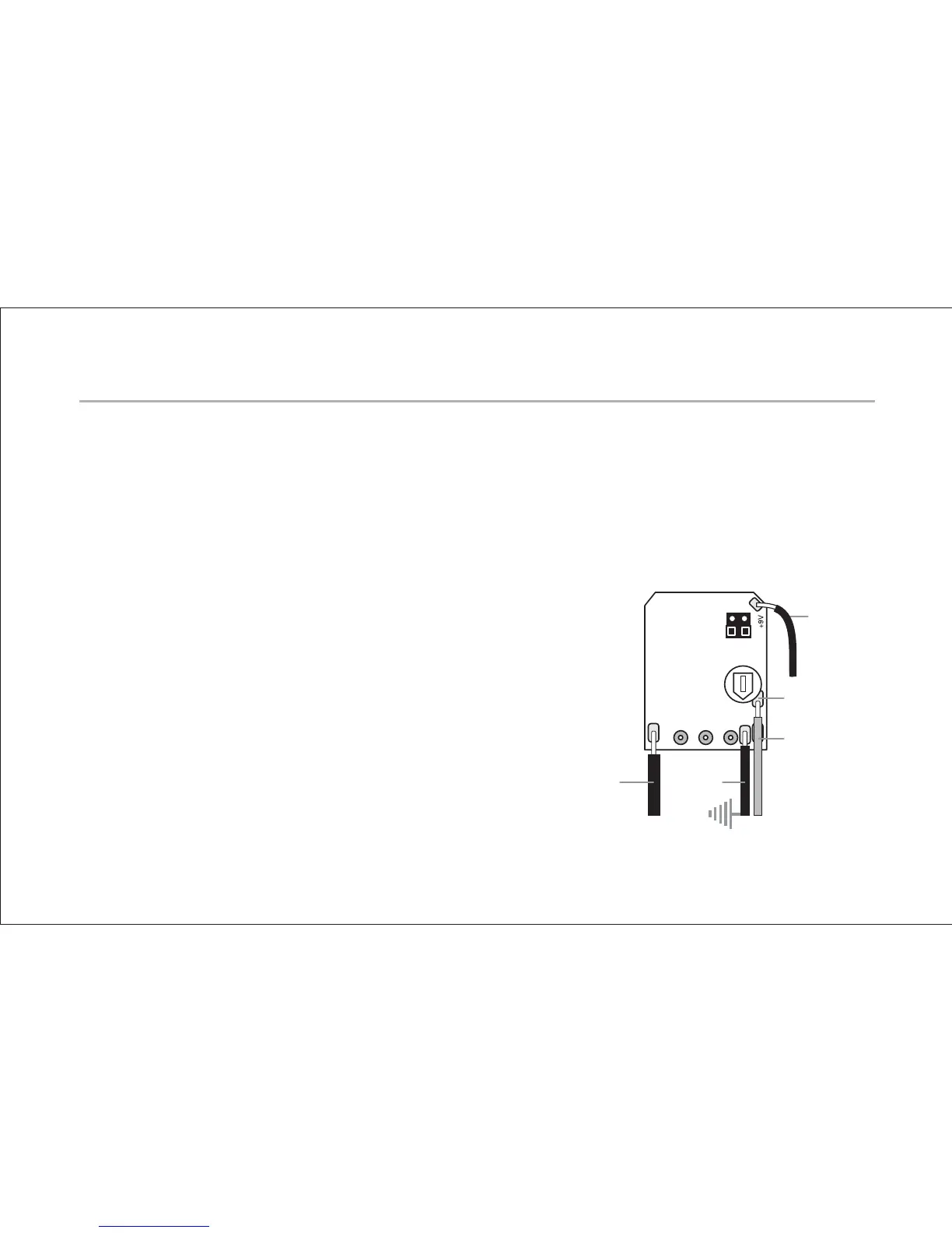
Warning: The solder pad terminals and the adjacent components on the
Powerchip circuit board are quite fragile and can be easily overheated. Use only
a low wattage soldering iron (30 watts max) to make your wire connections. To
best utilize the space inside the guitar, solder the wires to the circuit board so
that they exit toward the volume pot terminals.
1. Strip
3
⁄
32
” (2.4mm) and tin the wire ends of the pickups.
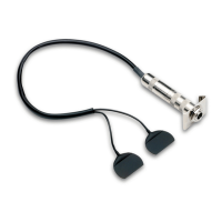
2. Solder the piezo pickup wire to the circuit board.
The pads are located on the side of the board
opposite the volume pot. The piezo hot wire
goes to the pad on the right edge of the
board, directly under and to the right of the
little white trimmer pot. Solder the piezo
ground wire (which should be left with the
braid intact) to the pad labeled “G” on the
right edge of the board, directly under the
piezo hot wire.
Red
Battery
Wire
Piezo Hot
Piezo Ground
Common
Ground
Output Ground
(Sleeve)
 Loading...