EasyManuals Logo

Ford 1955 User Manual

Ford 1955
16 pages
To Next Page IconTo Next Page
To Previous Page IconTo Previous Page
Page #12 background imageLoading...
Page #12 background image
10
Chapter
I
General
Engine
Repair
fuel
adjustment
to
obtain
the
smoothest
engine
idle
at
the
highest
manifold
vacuum
and/or
engine
r.p.m.
Reset
the
idle
speed
if
required.
(19)
ROAD
TEST.
Road
test
the
vehicle
as
a
final
check
on
the
work
performed.
Also,
notice
the
perform
ance
of
the
transmission,
axle,
brakes,
and
any
optional
accessories.
Recommend
any
additional
service
required
when
the
vehicle
is
delivered
to
the
owner.
3.
ENGINE
REMOVAL
AND
INSTALLATION
Separate
procedures
are
given
for
the
conventional
passenger
car
and
the
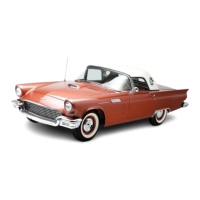
Thunderbird.
a.
Conventional
Passenger
Car.
The
following
procedures
apply
to
all
conventional
passenger
cars.
Differences
in
the
procedures
peculiar
to
vehicles
equipped
with
an
8
or
6-cylinder
engine
are
noted
when
they
exist.
The
procedures
given
are
for
the
engine
only,
without
the
transmission
attached.
Engine
compartment
toler
ances
make
it
impractical
to
remove
or
install
the
engine
with
the
transmission
attached.
(1)
REMOVAL.
If
the
vehicle
is
equipped
with
a
standard
or
overdrive
transmission,
follow
steps
(a)
and
(c).
If
the
vehicle
is
equipped
with
Fordomatic,
follow
steps
(b)
and
(c).
(a)
Steps
Peculiar
To
Standard
or
Overdrive
Transmission.
Disconnect
the
clutch
release
spring.
Remove
the
screws
retaining
the
equalizer
bar
support
to
the
flywheel
housing,
then
remove
the
support
and
bushing.
Disconnect
the
accelerator
linkage
at
the
mani
fold
bellcrank.
Remove
the
two
upper
flywheel
housing
bolts.
Remove
the
flywheel
housing
cover,
support
the
transmission
with
a
jack,
then
remove
the
remaining
flywheel
housing
bolts.
(b)
Steps
Peculiar
To
Fordomatic.
Disconnect
the
transmission
throttle
linkage
at
the
cross
shaft,
and
tie
the
linkage
to
the
dash
panel.
Remove
the
idler
arm
bracket.
Fold
back
the
floor
mat,
remove
the
two
rubber
plugs,
then
remove
the
two
top
converter
housing
to
engine
bolts.
Jack
up
the
front
of
the
vehicle
and
position
safety
stands.
Support
the
transmission
with
a
jack,
then
remove
the
remaining
converter
housing
to
engine
bolts.
Remove
the
converter
housing
lower
access
cover,
then
remove
the
six
converter
to
flywheel
assembly
bolts.
Remove
the
dip
stick
tube
assembly.
Remove
the
transmission
control
linkage
splash
shield
from
the
cylinder
block,
then
remove
the
oil
filter.
(c)
Engine
Removal.
Remove
the
hood.
Drain
the
cooling
system
and
the
crankcase.
Remove
the
heater
hoses.
On
vehicles
equipped
with
an
8-cylinder
engine,
remove
the
heater
inlet
duct.
On
vehicles
equipped
with
a
6-cylinder
engine,
remove
the
heater
blower
motor.
Remove
the
upper
and
lower
radiator
hoses,
then
remove
the
radiator.
Disconnect
the
battery
ground
cable
at
the
cylinder
block,
and
the
flex
fuel
line
at
the
fuel
pump.
Remove
the
fan.
Disconnect
the
windshield
wiper
vacuum
hose,
tem
perature
sending
unit
wire,
and
the
oil
pressure
sending
unit
wire.
Disconnect
the
primary
wire
at
the
coil.
Remove
the
starter
cable
at
the
starter
then
remove
the
starter.
Disconnect
the
ground
cable
from
the
rear
of
the
engine.
Remove
the
air
cleaner,
then
tape
the
air
horn
closed.
Disconnect
the
choke
cable
at
the
carburetor.
Disconnect
the
accelerator
linkage.
Disconnect
the
muffler
inlet
pipes
at
the
exhaust
manifold.
Attach
the
engine
lift
bracket
or
sling
(fig.
1
or
2).
Remove
the
right
and
left
front
splash
aprons.
Loosen
the
two
engine
front
steady
rest
to
frame
bolts.
Raise
the
vehicle
and
position
safety
stands.
On
8-cylinder
engines,
remove
the
left-hand
engine
support.
Remove
the
cap
screws
from
the
right-hand
engine
support
at
the
engine.
On
6-cylinder
engines,
remove
the
left-hand
mounting
bolts
at
the
insulator,
and
the
right-hand
mounting
nuts
at
the
engine.
Raise
the
engine
slightly,
then
carefully
pull
the
engine
from
the
transmission.
Carefully
lift
the
engine
out
of
the
engine
compartment.
Do
not
let
the
engine
swing
against
the
grille.
Install
the
engine
on
a
work
stand
using
the
appro
priate
engine
mount
(fig.
3
or
4).
Remove
the
engine
lifting
bracket
or
sling.
(2)
INSTALLATION.
If
the
vehicle
is
equipped
with
a
standard
or
overdrive
transmission,
follow
steps
(a),
(b),
and
(d).
If
the
vehicle
is
equipped
with
Fordo
matic,
follow
steps
(a),
(c),
and
(d).
(a)
Engine
Installation.
Install
the
appropriate
engine
lift
bracket
or
sling,
then
remove
the
engine
from
the
work
stand.
Lower
the
engine
carefully
into
the
engine
compartment.
On
8-cylinder
engines,
lower
the
engine
until
the
oil
pump
to
oil
pan
line
clears
the
left-hand
engine
support.
Start
the
transmission
main
drive
gear
into
the
clutch
disc.
On
Fordomatic
units,
start
the
converter
pilot
into
the
crankshaft.
NOTE:
On
standard
or
overdrive
units,
it
may
be
necessary
to
adjust
the
position
of
the
transmission
with
relation
to
the
engine
if
the
transmission
input
shaft
will
not
enter
the
clutch
disc.
If
the
engine
"hangs
up"
after
the
shaft
enters,
turn
the
crank-

Questions and Answers:

Question and Answer IconNeed help?

Do you have a question about the Ford 1955 and is the answer not in the manual?

Ford 1955 Specifications

General IconGeneral
BrandFord
Model1955
CategoryAutomobile
LanguageEnglish

Related product manuals