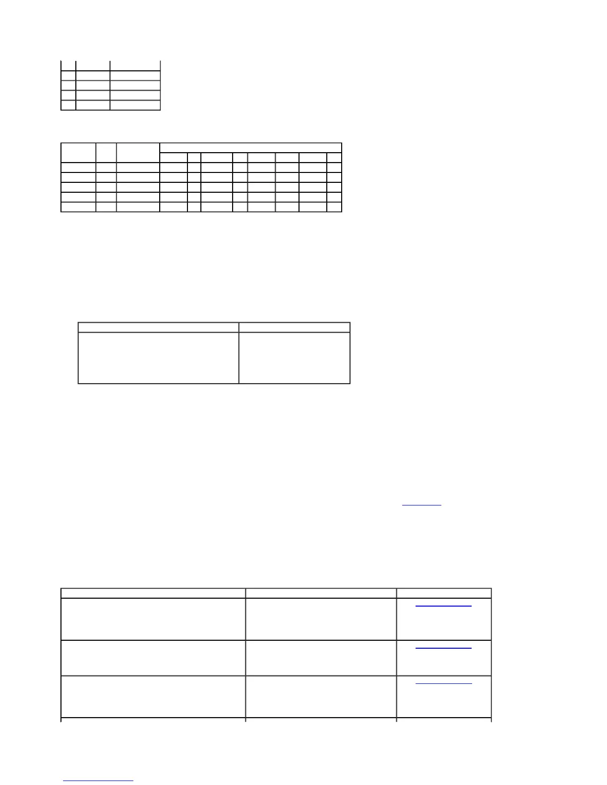
VACUUM APPLICATION CHART—MANUAL A/C
V = Vacuum
NV = No Vacuum
Inspection and Verification
1. Verify the customer's concern by operating the climate control system to duplicate the condition.
2. Inspect to determine if one of the following mechanical or electrical concerns apply:
Visual Inspection Chart
a
A leak in the vacuum control circuit may occur during acceleration (slow leak), may exist at all times (large leak), and may exist only when specific functions are selected (indicating
a leak in that portion of the circuit). The vacuum hoses used in the passenger compartment control circuit are constructed from PVC plastic material. The vacuum hoses used in the
engine compartment are constructed of Hytrel®. Because of the materials used, never pinch the vacuum hoses off during diagnosis to locate a leak. A wood golf tee can be used as
a plug when it is necessary to plug one end of the vacuum hose for leak test purposes.
3. If the inspection reveals obvious concern(s) that can be readily identified, repair as required.
4. If the concern remains after the inspection, connect the Rotunda New Generation Star (NGS) Tester to the data link connector (DLC) located beneath the instrument panel and select
the vehicle to be tested from the NGS menu. If the vehicle selection cannot be entered:
check that the program card is properly installed.
check the connections to the vehicle.
check the ignition switch position.
If the NGS still does not allow with the vehicle selection to be entered, refer to the New Generation Star Tester manual.
5. Perform the DATA LINK DIAGNOSTIC TEST using the NGS. If the NGS responds with:
CKT 914 and CKT 915 = ALL MODULE NO RESPONSE/NOT EQUIPPED, go to Communication System Diagnostics in Section 418-00 to diagnose network concern.
If the powertrain control module (PCM) is not listed for a communication concern, turn the A/C function selector switch to OFF and execute self-test diagnostics for the PCM.
6. If any PCM DTCs are retrieved, and are related to the concern, go to the Powertrain Control Module Diagnostic Trouble Code (DTC) Index to continue diagnostics.
7. If no DTCs related to the concern are retrieved, go to the Symptom Chart to continue diagnostics.
Symptom Chart
2 Yellow Floor/panel door
3 Black Vacuum source
4 — Not used
5 Blue Floor/panel door
6 Red Panel/defrost door
Switch Port Color Function
Function Selector Switch Position
MAX A/C A/C PNL/VENT OFF FLR/PNL FLOOR FLR/DEF DEF
1 White Recirc/fresh V NV NV V NV NV NV NV
2 Yellow Floor/panel NV NV NV V NV V NV NV
3 Black Vacuum source V V V V V V V V
5 Blue Full floor NV NV NV V V V V NV
6 Red Panel/defrost V V V NV V NV NV NV
Mechanical Electrical
Loose, missing or damaged A/C compressor drive belt.
Loose or disconnected A/C clutch.
Loose, misrouted or damaged vacuum lines.
Broken or leaking vacuum control motor.
a
Broken or leaking refrigerant lines.
a
Open fuses.
Blower motor inoperative.
A/C compressor inoperative.
Circuitry open/shorted.
Disconnected electrical connectors.
SYMPTOM CHART
Condition Possible Sources Action
Improper/erratic direction of airflow from outlet
Function selector switch.
A/C vacuum check valve.
Vacuum hose.
A/C vacuum reservoir tank and bracket.
Vacuum control motor.
Vacuum actuator arm.
GO to Pinpoint Test A.
Insufficient, erratic, or no heat
Low engine coolant level.
Engine overheating.
Plugged or partially plugged heater core.
Temperature blend door binding/stuck.
A/C electronic blend door actuator.
GO to Pinpoint Test B.
The A/C does not operate/does not operate properly
Fuse.
Circuitry short/open.
A/C cycling switch.
A/C system.
Function selector switch.
A/C refrigerant.
GO to Pinpoint Test C.
Page 3 of 301999 F-150/250 Workshop Manual
8/16/2010http://www.fordtechservice.dealerconnection.com/pubs/con...

 Loading...