10
ASSEMBLY
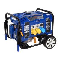
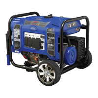
• Parts needed - Support leg & M8 screw (2).
Raise the front end of the generator high enough to gain access to the bottom of the frame. Securely position props
underneath to support.
•
• Line up holes on the support leg bracket to the holes on the front of the generator frame.
• Attach the support leg using M8 screws (2).
Fig 3
Installing Support Leg (See fig 3)
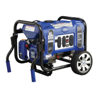
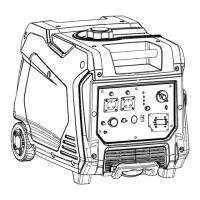
• Parts needed - 2 wheels, 2 axles, 2 hair pins, 2 washers, 2 hub caps and 2 self-tapping screws.
• Raise or tilt generator so you can slide the wheel axle pin into the wheel, the washer, the wheel mounting hole located
on the side of the frame.
• Secure the wheel assembly by reinserting a hair pin through hole at the end of the wheel axle and pressing until it locks
into place.
• Install hub cap to the wheel until “Click”. Install self-tapping screw, until the screw is snug.
• Repeat process on the other side of the generator to install the second wheel.
Attaching Wheels (See fig 2)
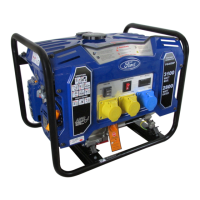
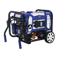
• Remove and discard the two RED shipping brackets and mounting hardware before starting the Generator.
Remove Shipping Bracket (See fig 1)
Fig 2Fig 1
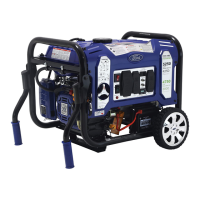
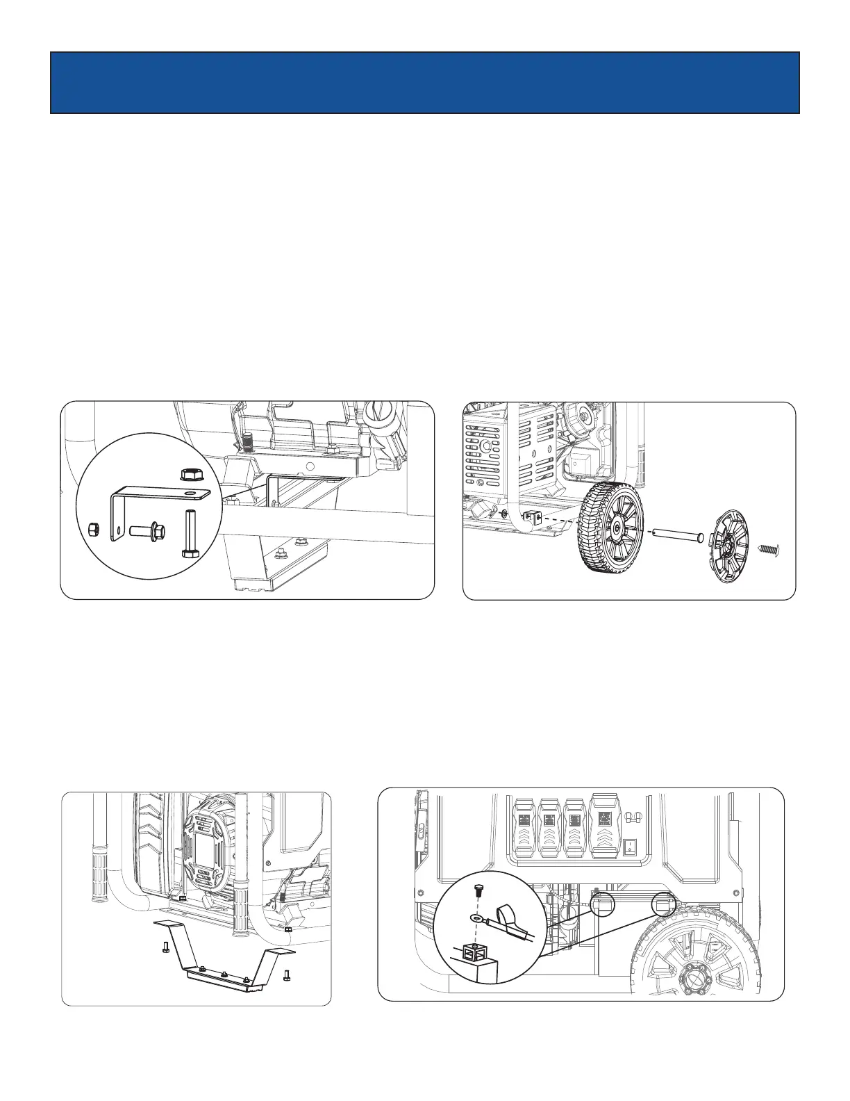
Fig 4
 Loading...