TECHNICAL DATA
NOTE:
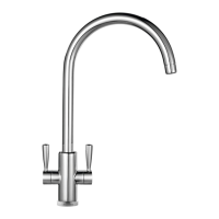
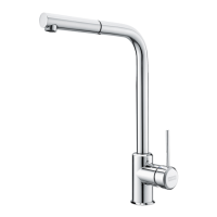
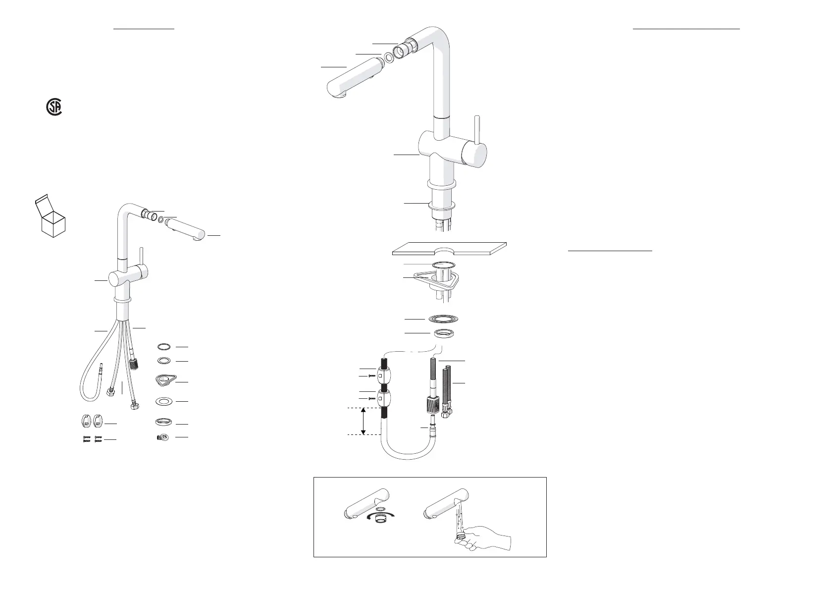
CONTENTS IN BOX
1 Pull out spray assembly
2 Rubber washer
3 Pull out hose
4 Faucet assembly
5 Rubber washer
6 Rubber washer
INSTALLATION INSTRUCTIONS
1. Remove all contents from the package and check for completeness.
3. Turn o water supply.
4
8
9
Flow Rate
Recommended Water Pressure
Max. Water Pressure
Recommended Hot Water Temp.
Hole Size For Faucet
Certies this faucet complies with ASME A112.18.1 / CSA B125.1
& NSF 61, NSF 372 and AB1953
1.75 GPM at 45 PSI
30-75 PSI
145 PSI
120°-140° F
1 3/8”
5
8
4
10
7
6
9
13
3
5
7
6
11
10
12
7 Plastic ange
13
3
12
12
11
2” (50 mm)
11
1
2
8 Fixing plate
9 Fixing nut
10 Pull out supply hose
11
Weights
12 Screws
13 Supply hoses
14 Aerator Wrench
1
2
3
3
2. Connect the pull out spray (1) to the pull out hose assy (3) hand tight.
Ensure the rubber washer (2) is in place.
4. Cut a mounting hole 1 3/8 diameter (35mm) in the desired position in
counter top or sink (if one isn’t available).
5. Place the rubber washer (5) over the hole.
ATTENTION: The washer should be sitting between the countertop and
faucet base.
DO NOT use putty or other sealant at this location.
NOTES:
Solid surface installation
: The countertop mounting surface needs to
be at and free of debris otherwise the faucet may not sit properly.
For tile installations, avoid installing faucet near or on top of grout lines.
This may cause a weak joint between the faucet and the counter and
could cause leaks.
6. Install the mounting hardware to the base of faucet body in
the following order - rubber washer (6), plastic ange (7),
xing plate (8) as shown.
7. Tighten with the xing nut (9) on the base of faucet body.
10. Connect the exible supply hoses (13) to the water supply in the
house.
11. Remove the aerator using 7/8” (22 mm) wrench, turn on water,
ush the faucet for any debris and check for leaks.
Reinstall the aerator and ensure everything is functioning properly.
8. Connect the pull out hose (3) to the pull out supply hose (10) using
the quick connect tting. Slide the quick connect tting sleeve to the
“open” position, insert the hose tting into the connector. You should
hear a “click”. Slide the sleeve to the “lock” position, you should hear
another “click”. This will ensure the tting is sealed and locked.
9.Place the weights (11) on the pull out hose (3) with the screws (12)
approximately 2” (50mm) above the bend in the bottom of the pull out
hose.
Contact us immediatly if you see inconsistencies.
Phone: (1- 800-626-5771)
website: www.frankeksd.com
email: ks-customerservice.us@franke.com
14
 Loading...