EasyManua.ls Logo

Fujitsu 9318739183 User Manual

Fujitsu 9318739183
12 pages
To Next Page IconTo Next Page
To Previous Page IconTo Previous Page
Page #11 background imageLoading...
Page #11 background image
En-11
Remote controller custom code setting
Use the following steps to select the custom code of the remote controller. (Note that the
air conditioner cannot receive a signal if the air conditioner has not been set for the cus-
tom code.)
(1) Press the START/STOP button until only the clock is displayed on the remote control-
ler display.
(2) Press the MODE button for at least 5 seconds to display the current custom code
(initially set to A).
(3) Press the SET TEMP. () () button to change the custom code between
ABCD. Match the code on the display to the air conditioner custom code.
(4) Press the MODE button again to return to the clock display. The custom code will be
changed.
If no buttons are pressed within 30 seconds after the custom code is displayed, the
system returns to the original clock display. In this case, start again from step 1
The air conditioner custom code is set to A prior to shipment.
The remote controller resets to custom code A when the batteries in the remote control-
ler are replaced. If you use a custom code other than custom code A, reset the custom
code after replacing the batteries.
If you do not know the air conditioner custom code setting, try each of the custom codes
(ABCD.) until you find the code which operates the air conditioner.
12. TEST RUN
WARNING
Do not turn on the power until all installation work is complete.
CAUTION
Always turn on the power 12 hours prior to the start of the operation in order to ensure
compressor protection.
Check items
(1) Is operation of each button on the remote control unit normal?
(2) Does each lamp light normally?
(3) Do air ow direction louvers operate normally?
(4) Is the drain normal?
(5) Do not have an abnormal noise and vibration during operation?
• Do not operate the air conditioner in test run for a long time.
[Operation method]
• For the operation method, refer to the operating manual.
The outdoor unit may not operate depending on the room temperature.
In this case, press the test run button on the remote controller while the air conditioner is
running.
(Point the transmitter section of the remote controller toward the air conditioner and press
the test run button with the tip of a ballpoint pen, etc.)
Transmitter section
TEST RUN button
• To end test operation, press the remote controller START/STOP button.
(When the air conditioner is running by pressing the TEST RUN button, the OPERA-
TION Lamp and TIMER Lamp will simultaneously ash slowly.)
[Using the wired remote control] (Option)
For the operation method, refer to the operating manual.
(1) Stop the air conditioner operation.
(2) Press the MODE button and the FAN button simultaneously for 2 seconds or more to
start the test run.
Test run display
(3) Press the START/STOP button to stop the test run.
13. CUSTOMER GUIDANCE
Explain the following to the customer in accordance with the operating manual:
(1) Starting and stopping method, operation switching, temperature adjustment, timer, air
ow switching, and other remote control unit operations.
(2) Air lter removal and cleaning, and how to use the air louvers.
(3) Give the operating manual to the customer.
14. ERROR CODES
If you use a wireless remote controller, the lamp on the photo detector unit will output error
codes by way of blinking patterns. If you use a wired remote controller, error codes will ap-
pear on the remote control display. See the lamp blinking patterns and error codes in the
table. An error display is displayed only during operation.
Error display
Wired
remote
controller
Error code
Description
OPERATION
lamp
(green)
TIMER
lamp
(orange)
ECONOMY
lamp
(green)
(1)
(1)
Serial communication error
(1)
(2)
Wired remote controller
communication error
(1)
(5)
Check run unfinished
(2)
(1)
Unit number or Refrigerant circuit
address setting error
[Simultaneous Multi]
(2)
(2)
Indoor unit capacity error
(2)
(3)
Combination error
(2)
(4)
• Connection unit number error
(indoor secondary unit)
[Simultaneous Multi]
• Connection unit number error
(indoor unit or branch unit)
[Flexible Multi]
(2)
(7)
Primary unit, secondary unit set-
up error [Simultaneous Multi]
(3)
(2)
Indoor unit PCB model
information error
(3)
(5)
Manual auto switch error
(4)
(1)
Room temp. sensor error
(4)
(2)
Indoor unit Heat Ex. Middle temp.
sensor error
(5)
(1)
Indoor unit fan motor error
(5)
(3)
Drain pump error
(5)
(7)
Damper error
(5)
(8)
Intake grille error
(5)
(15)
Indoor unit error
(6)
(2)
Outdoor unit main PCB model
information error or
communication error
(6)
(3)
Inverter error
(6)
(4)
Active filter error, PFC circuit er-
ror
(6)
(5)
Trip terminal L error
9318739183_IM.indb 119318739183_IM.indb 11 11/19/2014 6:04:32 PM11/19/2014 6:04:32 PM
Question and Answer IconNeed help?

Do you have a question about the Fujitsu 9318739183 and is the answer not in the manual?

Fujitsu 9318739183 Specifications

General IconGeneral
BrandFujitsu
Model9318739183
CategoryAir Conditioner
LanguageEnglish

Summary

Safety Precautions

Important! Please read before starting

Key safety and operating standards for installers/service personnel.

Special precautions

Specific safety advice for wiring, transporting, and installation.

About This Product

Precautions for using R410A refrigerant

Important considerations and differences when using R410A refrigerant.

Special tools for R410A

Lists and describes special tools required for R410A refrigerant systems.

Accessories

Lists the installation accessories supplied with the indoor unit.

Additional materials required for installation

Lists materials that are necessary but not supplied for installation.

Optional parts

Lists optional parts available for the air conditioner.

General Specifications

Type of copper pipe and insulation material

Details specifications for copper pipes and insulation materials used.

Selecting the Installation Location

Location Criteria

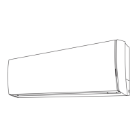
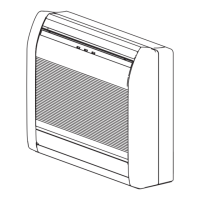
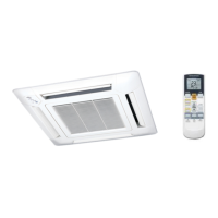
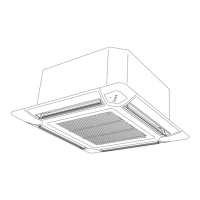
Guidelines for selecting the indoor unit installation location.

Installation Work

Installation dimensions

Specifies the required dimensions and clearances for unit installation.

Indoor unit piping direction

Illustrates the different piping directions possible for the indoor unit.

Cutting the hole in the wall for the connecting pipes

Instructions for cutting the wall opening for pipes and ensuring proper drainage.

Installing the wall hook bracket

Detailed steps for securely mounting the wall hook bracket.

Forming the drain hose and pipe

Guidance on shaping and connecting the drain hose and refrigerant pipes.

Flare connection (Pipe connection)

Instructions for making flare connections for refrigerant pipes.

Bending pipes

Advice on bending refrigerant pipes without causing damage or hardening.

Pipe connection

Instructions for connecting refrigerant pipes using flare nuts and torque wrench.

Electrical Wiring

Wiring system diagram

Provides a diagram illustrating the electrical wiring connections.

Finishing

Insulating pipes and securing cables

Details on insulating pipes and fastening connection cables for a neat finish.

Front Panel Removal and Installation

Intake grille removal and installation

Steps for removing and installing the indoor unit's intake grille.

Front panel removal and installation

Procedure for safely removing and reinstalling the front panel of the unit.

Remote Controller Installation

Remote controller holder installation

Instructions for mounting the remote controller holder on a wall or pillar.

Optional Kit Installation

Before installing wired remote controller

Important considerations before installing a wired remote controller.

Remote controller cable modification

Steps for modifying the remote controller cable for connection.

External input / output Wire modification

Instructions for modifying external wires for optional kits.

Front panel, control box cover and display case removal

Procedure for removing the front panel, control box cover, and display case.

Connecting cable to control board connector

Guide for connecting cables to the indoor unit's control board.

Function Setting

Entering the Function Setting Mode

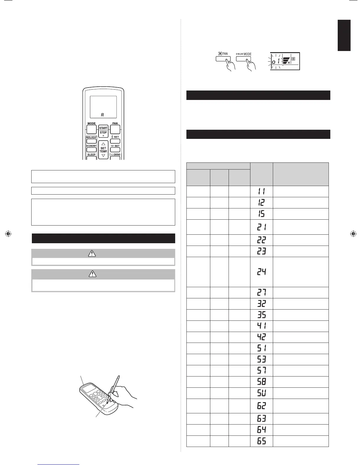
Steps to access the function setting mode using the remote controller.

Selecting the Remote Controller Custom Code

Procedure to select the custom code for the remote controller.

Selecting the Function Number and Setting Value

Guide on selecting function numbers and their corresponding setting values.

Function details: Filter Sign

Configuration for the filter sign display interval based on air dust.

Function details: Auto Restart

Enables or disables automatic restart after a power interruption.

Function details: Room temperature sensor switching

Setting for switching between indoor unit and wired controller sensors.

Function details: Remote controller custom code

Setting to change the indoor unit custom code for wireless controllers.

External input control

Control modes for external input, such as operation/stop or forced stop.

Room temperature sensor switching (Aux.)

Setting for using the temperature sensor on the wired remote controller only.

Indoor unit fan control for energy saving for cooling

Enables/disables power-saving fan control when the outdoor unit is stopped.

Temperature correction

Adjusting temperature sensor readings for optimal cooling/heating performance.

Test Run

Check items

List of checks to perform during the test run operation.

Operation method

Instructions on how to perform the test run operation.

Customer Guidance

Customer Explanation Points

Key information to explain to the customer regarding operation and maintenance.

Error Codes

Error Code Table

Table listing error codes, blinking patterns, and their descriptions.

Related product manuals