En-11
15. CUSTOMER GUIDANCE
Explain the following to the customer in accordance with the operating manual:
(1) Starting and stopping method, operation switching, temperature adjustment, timer, air
fl ow switching, and other remote control unit operations.
(2) Air fi lter removal and cleaning, and how to use the air louvers.
(3) Give the operating manual to the customer.
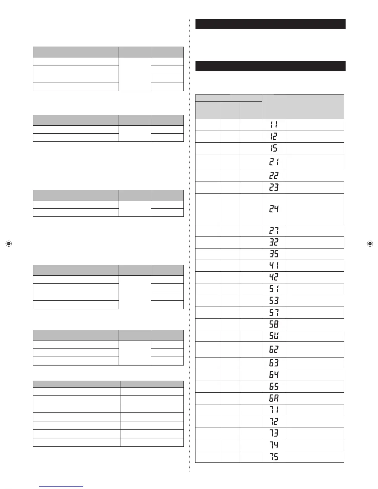
16. ERROR CODES
If you use a wireless remote controller, the lamp on the photo detector unit will output er-
ror codes by way of blinking patterns. If you use a wired remote controller, error codes will
appear on the remote controller display. See the lamp blinking patterns and error codes in
the table. An error display is displayed only during operation.
Error display
Wired
remote
controller
Error code
Description
OPERATION
lamp
(green)
TIMER
lamp
(orange)
ECONOMY
lamp
(green)
●
(1)
●
(1)
◊
Serial communication error
●
(1)
●
(2)
◊
Wired remote controller
communication error
●
(1)
●
(5)
◊
Check run unfinished
●
(2)
●
(1)
◊
Unit number or Refrigerant
circuit address setting error
[Simultaneous Multi]
●
(2)
●
(2)
◊
Indoor unit capacity error
●
(2)
●
(3)
◊
Combination error
●
(2)
●
(4)
◊
• Connection unit number
error (indoor slave unit)
[Simultaneous Multi]
• Connection unit number error
(indoor unit or branch unit)
[Flexible Multi]
●
(2)
●
(7)
◊
Master unit, slave unit set-up
error [Simultaneous Multi]
●
(3)
●
(2)
◊
Indoor unit PCB model
information error
●
(3)
●
(5)
◊
Manual auto switch error
●
(4)
●
(1)
◊
Room temp. sensor error
●
(4)
●
(2)
◊
Indoor unit Heat Ex. Middle temp.
sensor error
●
(5)
●
(1)
◊
Indoor unit fan motor error
●
(5)
●
(3)
◊
Drain pump error
●
(5)
●
(7)
◊
Damper error
●
(5)
●
(8)
◊
Intake grille error
●
(5)
●
(15)
◊
Indoor unit error
●
(6)
●
(2)
◊
Outdoor unit main PCB model
information error or
communication error
●
(6)
●
(3)
◊
Inverter error
●
(6)
●
(4)
◊
Active filter error, PFC circuit
error
●
(6)
●
(5)
◊
Trip terminal L error
●
(6)
●
(10)
◊
Display PCB microcomputers
communication error
●
(7)
●
(1)
◊
Discharge temp. sensor error
●
(7)
●
(2)
◊
Compressor temp. sensor error
●
(7)
●
(3)
◊
Outdoor unit Heat Ex. liquid
temp. sensor error
●
(7)
●
(4)
◊
Outdoor temp. sensor error
●
(7)
●
(5)
◊
Suction Gas temp. sensor error
Heating Room Temperature Correction
Depending on the installed environment, the room temperature sensor may require a cor-
rection.
The settings may be changed as shown in the table below.
(♦... Factory setting)
Setting Description
Function
Number
Setting Value
♦ Standard
31
00
Lower control 01
Slightly warmer control 02
Warmer control 03
Auto Restart
Enable or disable automatic system restart after a power outage.
(♦... Factory setting)
Setting Description
Function
Number
Setting Value
♦ Yes
40
00
No 01
* Auto restart is an emergency function such as for power failure etc. Do not start and stop
the indoor unit by this function in normal operation. Be sure to operate by the control unit,
or external input device.
Indoor room temperature sensor switching function
(Only for wired remote controller)
The following settings are needed when using the wired remote controller temperature
sensor.
(♦... Factory setting)
Setting Description
Function
Number
Setting Value
♦ No
42
00
Yes 01
* If setting value is “00” :
Room temperature is controlled by the indoor unit temperature sensor.
* If setting value is “01” :
Room temperature is controlled by either indoor unit temperature sensor or remote con-
troller unit sensor.
Remote controller signal code
Change the indoor unit Signal Code, depending on the remote controllers.
(♦... Factory setting)
Setting Description
Function
Number
Setting Value
♦ A
44
00
B01
C02
D03
External input control
“Operation/Stop” mode or “Forced stop” mode can be elected.
(♦... Factory setting)
Setting Description
Function
Number
Setting Value
♦ Operation/Stop mode
46
00
(Setting forbidden) 01
Forced stop mode 02
Setting record
Record any changes to the settings in the following table.
Setting Description Setting Value
Filter sign
Cooler room temperature correction
Heater room temperature correction
Auto restart
Indoor room temperature sensor switching function
Remote controller signal code
External input control
After completing the FUNCTION SETTING, be sure to turn off the power and turn it on
again.
9319357003-02_IM_EN.indd 119319357003-02_IM_EN.indd 11 7/27/2011 3:43:40 PM7/27/2011 3:43:40 PM
 Loading...